
Introduction
On this section you can find a short Manual for the Triangulation Sensor : How to switch on the machine, the precautions to take and the software "ScanArea3".
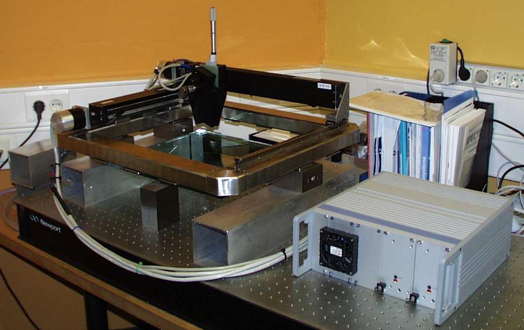
Description of the Triangulation Sensor
A triangulation sensor determines the distance an object using trigonometric characteristics. Triangulation can be done by determining two solid lines in a plane crossing at a prominent point. Triangulation sensors project a bright spot onto a surface by focusing a laser beam on it. This has two advantages :
- There is a feature on the surface which is easy to detect.
- The projected point can only be along the optical axis of this laser beam.
One solid line is given by this axis. A lens watches this point from beside. The lens images the spot on the surface into a linear CCD to determine the position of the spot. Now we can determine the angle of the second solid line. Since one point of the second solid line is fixed at the center of the lens, the position of the spot is evaluated.
Some precautions before using the measuring machine.
- The head of the devive is very fragile. Be careful when you install an object to measure.
- Never change the angle of the head. All the calculations are realized with the current angle.
 |
To resume, don't touch the head ! Only the gray screw to calibrate the sensor. | |
Power on the PC and starting the Software.
First you must switch on the PC and the measuring machine, after login.
Remove the blue bag on the measuring machine.
- Power on
- The PC
- The controller.
- Login on PC
- Name : ins
- Password : insins
Before starting the measurements, you must wait for 30 minutes. The head of the sensor is cold at the beginning. If you calibrate without first waiting 30 minutes, you will have an error on each value of your measurements.
Now all the device is ready to take a measurement.
How to start the software. The name of the software is "ScanArea3".
On the desktop you will see the shortcut to this software :  Double click on this icon and the software will start.
The Software ScanArea3
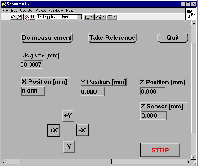
When you start this software you will see this window :
To start this program, you must open the menu "Operate", and click on "Run". There is a shortcut in this window, it's the white arrow : ![]() that you can see under the menu "Edit" on the left.
that you can see under the menu "Edit" on the left.
When starting this software, you must be very careful. The software must initialize the sensor. The program will ask you this question :
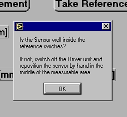
When you switch off the software ScanArea3, the program will move the Sensor well inside the reference switches. When you are sure that the sensor is well inside the reference switches, click "OK". Even if you are not sure, you must follow the procedure, "If not, sw...". You must swich off the program correctly. Like this, the program moves the Sensor to the good position. You will be able to read the procedure at the end of this document.
The panel ScanArea3.
The command buttons.
This section explains some of the features of the panel ScanArea3.
There are eight buttons on this command panel, there are explained in the Table 1 :
| This button opens a new window for Taking measurements. | |
| Take reference is a function which can save the mecanical imperfections onto a reference file. | |
| This button permits you to quit the program correctly. You MUST quit before closing the window ScanArea3. | |
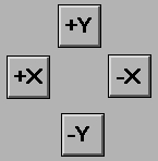 |
You can move the sensor along the axis X and Y with these four buttons. You can choose the size of your displacement with the "Jog size" window. |
 |
To stop the measurements. |
On this panel you can see some information on the position of the sensor, see Table 2 :
 |
This gives you the position of the sensor on the axis X. |
 |
This gives you the position of the sensor on the axis Y. |
 |
This gives you the height of your measurement point with regard to the reference plane. |
 |
This gives you the height compared to your reference point. |
How to displace the sensor
You can move the sensor with the buttons, ![]() ,
, ![]() ,
, ![]() or
or ![]() .
.
But first you must choose the step of your displacement. For that you must use the "Jog size [mm]" part, 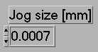 , on the panel ScanArea.
There are two way to choose the size of your displacement. You can use the black arrow, and you increase or reduce the value of your displacement, 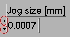 .
.
Or you click on the window where there is the number (here 0.0007) and you choose your value.
How to calibrate the sensor
Now, you must calibrate correctly the height of the sensor and you must move the sensor into a good position to make the measurements.
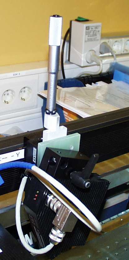
First you must move the sensor into the good range of measurement. The distance between the surface and the sensor is 48 mm (without glass between the sensor and the surface).
On the left of the sensor's head three LEDs, two red and one green.
- The left red LED will switch on if you are out of range.
- The red LED on the middle will switch onif there is not enough light to make a measurement.
- The green LED indicates that the laser is on.
To take a measurement, the two red LEDs must be switched off and the green LED must be switched on.
- Turn the black ring (under the gray screw) to the left.
- Turn the gray screw until the two red LEDs switch off.
Now correct the height of the sensor. Choose a reference point on the surface you want to study.
- Turn the grey screw continuously until you read 0.000 on the window Y position [mm], .
- Verify if the two red LEDs are always off.
How to take a reference
Why must we take a reference file ?
Before each series of measurements you should take a reference. However, this is not necessary if you work under the same conditions every time (same temperature, same place...). As the temperature changes, the weight of the head which twists the axis, the mechanical structure is not perfect, etc. the sensor doesn't travel a plan. So to compensate the height's difference you must know the surface that the head travels. For that you take a very flat surface and you scan all the area of the measuring machine. Here is the procedure.
Click on the button ![]() and two new panels will open. SetShapeOfArea and Take Reference.
and two new panels will open. SetShapeOfArea and Take Reference.
Panel SetShapeOfArea.
The panel SetShapeOfArea is explained in the section 'How to take a measurement'.
Panel Take Reference.
This panel permits you to choose the surface you want to scan (see the panel Take Reference figure 3).
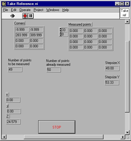
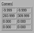 |
The corner of the surface for the reference plane (the maximum and the minimun point of the surface). First columns : Axis X. Second columns : Axis Y. |
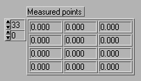 |
Give you information on the measured points. First columns : Axis X, second columns : Axis Y,third columns : Axis Z (the height). |
  |
The program informs you what it must do and what it made. |
 |
The program gives you the step between two points. |
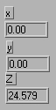 |
The program gives you the position of the sensor. |
 |
To stop the measurement process. |
How to take a measurement
Now we can start the procedure for the measurements.
|
After taking measurement, when you will want to see your result with the software "AnalyseSurface", you will need two files of the same surface. Fo this reason, you must take two measurements of the same surface with the sames parameters. |
- Click on the button
 .
.
- The program asks you this question (You have got the possibility to repeat measurements):
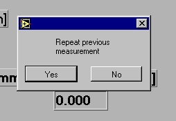
If you say "Yes" the software memorizes the points at which define the area of measurements. Iif you click "No", the software resets the values.
After the answer, the program opens a new window (GetCornerPointC).
Panel GetCornerPointsC.
On this panel you choose the corners of the surface you want to study (see Figure 5).
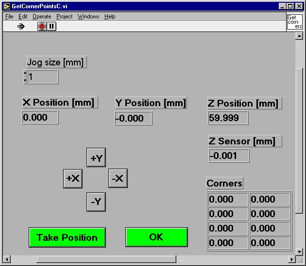
- With the button of displacement
 ,
,  ,
,  ,
,  and the window "Jog Size" choose a corner.
 - Click on the button
 . The software memorizes the first corner.
 - Repeat 1. and 2. for the others corners. You must take four points.
After memorizing the four corners the software opens a new window (SetShapeOfArea, see Figure 6).
Panel SetShapeOfArea.
On this part you will need to give some information about the surface you wish to examine and the distance between two points for your study.
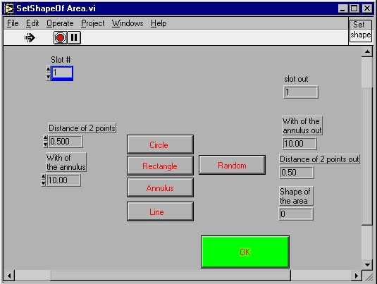
In this table you find the information about the button you can use for the panel SetShapeOfArea.
 |
Information for the software. Do not change this ! |
| You choose the distance between two points of measurement. | |
 |
If you wish to include the surface of an annulus in your measurement, you must enter the internal diameter here. |
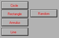 |
Click on the surface you wish to study. |
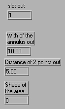 |
Recall of the information you give to the software on this panel. |
 |
Click here to confirm your choice. |
After giving the information on the surface and the distances of two points,
- click "OK".
The window SetShapeOfTheArea will shut up and another window will open (Enter Z linear translator.vi).
Enter Z linear translator
Enter Z linear translator permits the software to take measurements with regard to a reference plan.
Enter the Z value of the linear translator here. You can read this number on the gray screw. This machine uses a reference plane just under the frame. The software makes its calculations with regard to this plane.
- Click OK to confirm.
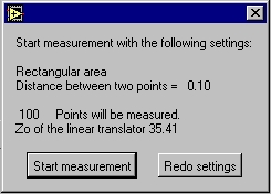
Start measurement box.
The software opens a dialog box. You have got the choice between two possibilities (see figure 8) :
- Confirm your choice, click "Start measurement"
- Change values "Redo settings" This function aborts the procedure and opens the "GetCornetPointsC" window to restart the procedure.
Save measured data.
When the measurements are finished, the software asks you if you want to save the data (Figure 9).
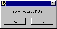
- Click No to return to the window ScanArea3.
- Click Yes to open a new window opens (see figure 10).
EnterRemeark
Before saving the data you have an option to enter a description for your own reference.
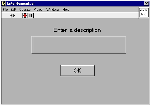
Here you can give all the information about your surface, what you are doing...
- Click OK to confirm.
Choose file to write
The "Choose file to write" box opens :
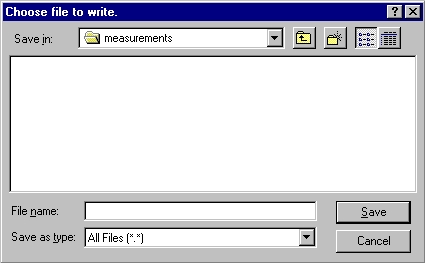
- Save your data in the directory d:\measurements .
- Give the name of your file in the file name box with the extension ".txt".
- Click "Save".
You come back to the window ScanArea3, the measurements are finished and your data is saved onto your file.
How to quit the software ScanArea3
You can't quit ScanArea3 during the measuring procedure. You must finish the sequence. When you see the panel ScanArea3, you click on the button![]() . The software moves the sensor correctly on the well position reference. After you quit the program with the file menu of Labwiev (the software which permit to write the software ScanArea3) and you click Exit (Ctrl Q, for the shortcut).
. The software moves the sensor correctly on the well position reference. After you quit the program with the file menu of Labwiev (the software which permit to write the software ScanArea3) and you click Exit (Ctrl Q, for the shortcut).
- Click
 on the panel ScanArea3. Wait for the sensor to move well inside the reference switches.
Quit Labwiev.
- Open the menu "File" and click on "exit" (shortcut : Ctrl + q).
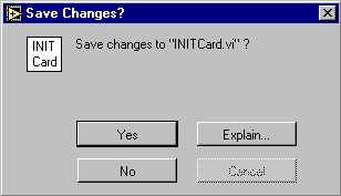
This procedure opens a dialogue box. It will ask whether you want to save the file INIT Card.vi (see figure 12).
- Here is the dialog box "Save Changes?". Click "No".
The software is closed.
Now you can study your surface with the software AnalyseSurface. Or if you have finished, you switch off the sensor and the computer.
Don't forget to cover up the measuring machine with the blue bag, and to clean the work space. Thank you !