Performance and limitations
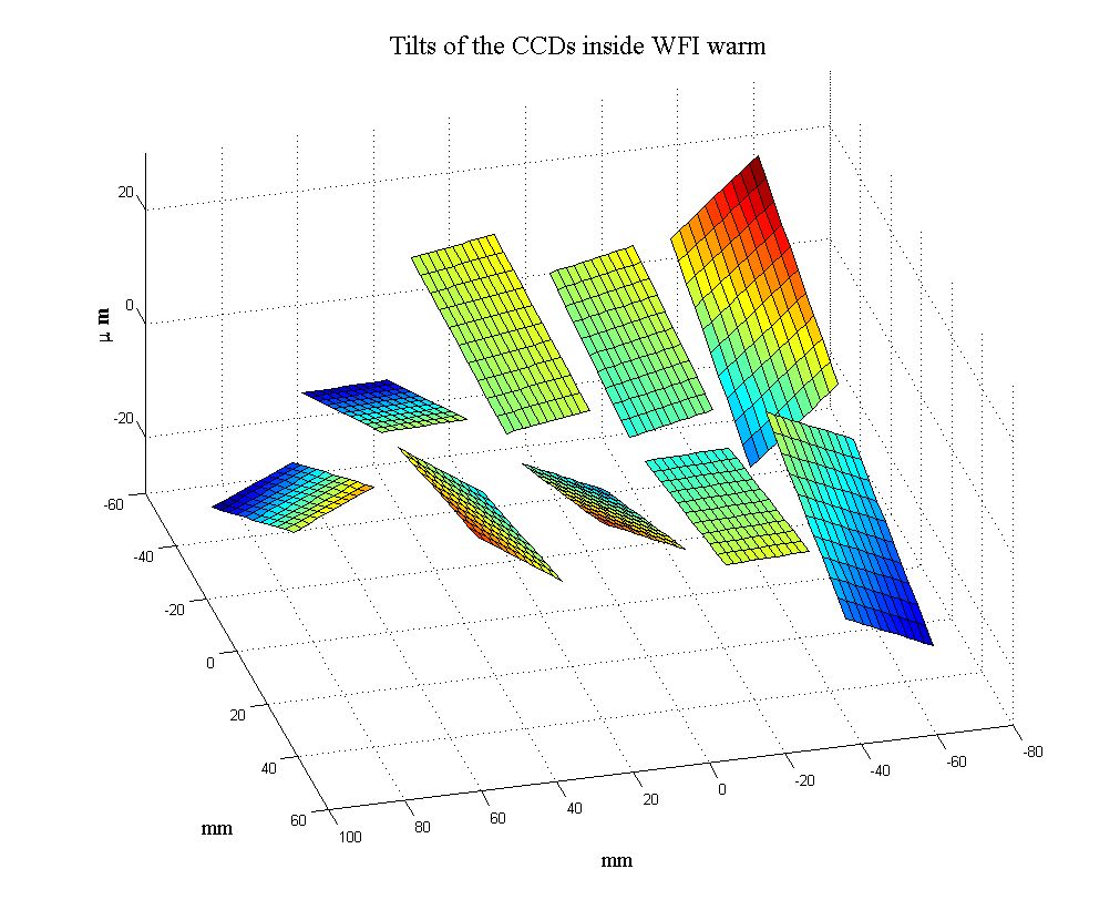
Performance The measuring device can measure areas with a maximum size of 300 mm by 300 mm with repeatability in Z direction of 1 mm RMS on the whole area. The position accuracy in X and Y is limited by the 130 mm diameter of the laser spot of the triangulation sensor. However, X and Y accuracy is not as critical because CCD surfaces are very flat over distances much larger than the spot size. The instrument can measure 100 points equally distributed over the area of a standard 2k x 4k CCD,15 mm (30 mm x 60 mm) in less than 1 minute.The tip and tilt of the CCD can then be determined to an accuracy of 0.1 mrad.The process of a measurement is as follows: After the dewar is put underneaththe device and aligned with respect to the X and Y axis, the triangulation sensor is moved to a position above the CCD to be measured in a manual position mode. Then the triangulation sensor is moved in Z direction so that the CCD surface is in the middle of its measurable range (5 mm). The laser spot is moved to the 4 corners of the CCD and these positions are recorded. The user selects the distance between the points to be measured and the CCD is then scanned with the defined resolution. This process is repeated for each CCD in a mosaic. It is also possible to scan circular and annular areas, as it is necessary to measure a dewar flange or window as a reference surface. The best-fit plane is calculated from each set of measurements of the referencesurface and the CCDs. The tip, tilt and offset parameters of a CCD with respect toa reference surface indicate the alignment and corrections to be applied. Thetilt and offset of the CCDs in a mosaic can be displayed in surface plots,as shown below: |
Limitations The measuring device is not perfect, since the window in front of the CCD influences the measurement in two ways:
|
| Tilts of the CCDs inside WFI at roomtemperature
|