The VLTI Control System
Fringe Tracking
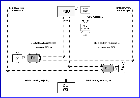
The following drawing shows a scheme of the fringe control loop architecture.

Just as adaptive optics reduces the image blur induced by the atmosphere inconventional single telescope observations, Fringe Tracking, orcophasing, reduces the blur in interferometric observations. The fringe tracking control system includes the following main components:
- the Fringe Sensor Unit (FSU)
- the OPD Controller (OPDC)
- the Delay Line (DL)
- the Beam Tracking controller (BTK)
- the IRIS Fast Guiding controller (IFG)
- the accelerometer-based vibration compensation system (MANHATTAN2)
- the adaptive Vibration Tracking compensator (VTK)
Measurementof the OPD between starlight beams is performed by the FSU FINITO (Fringe Tracking Instrument of Nice and Torino). The measured OPD issent to the OPDC which then applies a correction signal to the DL in order to minimize the residual OPD.
At the beginning of a VLTI observation the beams are aligned, to maximize the injection on the mono-mode fibers at the entrance FINITO, using the Beam Tracking controller which works by injecting a circular tip/tilt modulation and detecting the beam displacement by synchronous demodulation of the photometric flux.
Low frequency (up to 5 Hz) residualtip/tilt jitter in the lab, which severely degrades injection, is attenuated by the IFG controller which operates in open loop, by detecting the beam displacement on IRIS and addressing the commands toa Tip-Tilt Platform located downstream the dichroic separating the beams fed to FINITO and IRIS.
Once the beam is centered and IFG is enabled, a phase of fringe detection explores a relevantrange of OPD in order to identify the appropriate operating region around the point of path balancing. This phase involves both the DLsubsystem and the FSU FINITO. The DLs are controlled in blind mode,following the nominal trajectory provided by the OPD model, plus a superposed OPD offset, continuous or step-wise, to scan a path length around the predicted fringe position. Meanwhile, FINITO operates its temporal OPD modulation to detect fringes.
Once fringesare detected, the DL control system offsets the nominal trajectory bythe delay computed by FINITO and VLTI switches to fringe tracking mode.Then the system switches to the proper observation mode, in which FINITO provides the information for OPD stabilisation and the instrument integrates on the scientific target.
Despitethe high construction standards and outstanding mechanical stability of the telescope support structure, micro vibrations of the order of one wavelength (1 to 2 μm) still propagate to the mirrors at frequencies beyond the bandwidth (circa 15 Hz) of the closed loop fringe trackingsystem.
Vibrations imparted to the primary, secondary and tertiary mirrors of the UTs are currently measured by a grid of suitably placed accelerometers, converted to optical path lengths and cancelled by a wideband feed-forward compensation algorithm (MANHATTAN2) forwarding additional real-time corrections to the DL.
TheVTK compensator, based on an adaptive narrow band cancellation algorithm, can attenuate remaining vibrations measured on the stellar signal on condition that they are sufficiently stable in amplitude and frequency.
