The VLTI Control System
Control Hardware
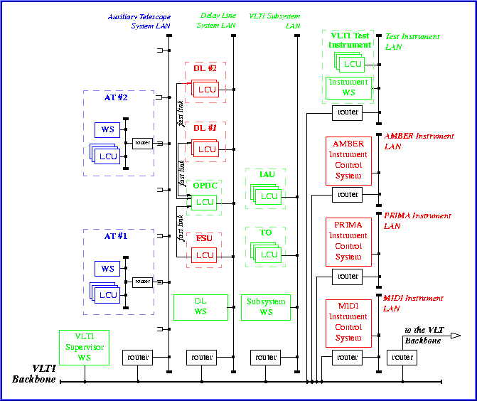
Because of the number, the heterogeneity and the locations of the Interferometer components, the VLTICS is based on a distributed,multi-platform, network-based architecture. Local Control Units (LCUs), composed by a VME backplane equipped with CPU boards and interface cards, perform real-time control of VLTI subsystems. Multi-user multi-tasking workstations (WSs) run high-level coordinating tasks and the graphical user interface software. Network links provide the communication layer among all the computing nodes and a dedicated Time Bus will convey the time synchronization signal.
Each main system has a dedicated LAN that is connected to theVLTI and the VLT backbone LAN by means of routers. The VLTI backbone LAN is realised by a network of ATM switches and is linked to the backbone LAN of the UTs.
Four LCUs, a coordinating WS and a LAN realise the control hardware of each AT. The DL LAN gathers the DL and VCM controllers, the OPD Controller and the Fringe Sensor Unit LCUs. The reflective memory network ties together the LCUs participating in the fringe control loop. All LCUs on the four UT Coudé trains are gathered on one dedicated LAN. The ISS and data flow WS are gathered on another dedicated LAN.
The concept of the hardware architecture of the VLTI Control System is shown in the following figure.

