
Offered coronagraphic modes
Different masks are offered for coronographic observations:
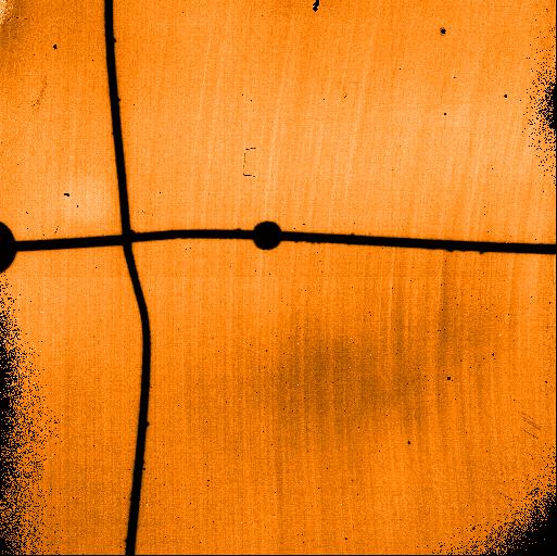
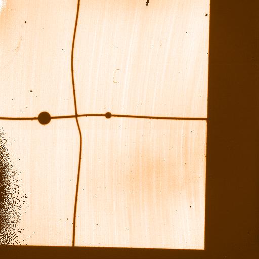
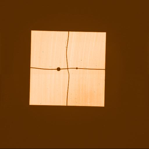
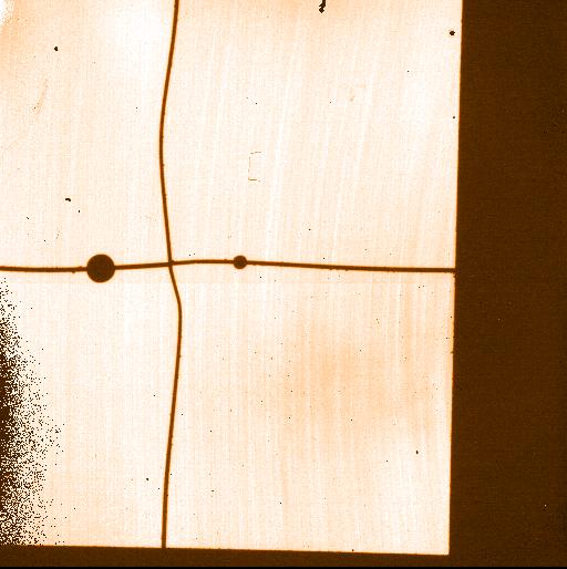
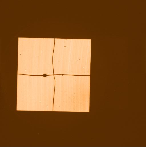
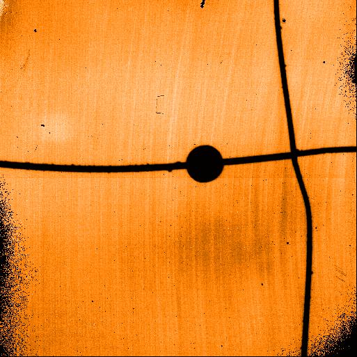
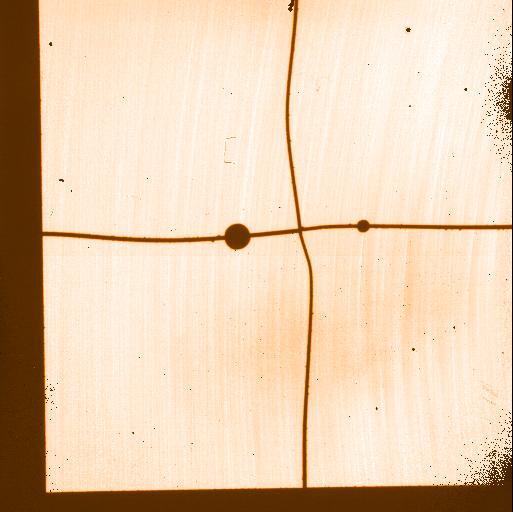
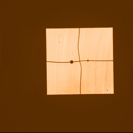
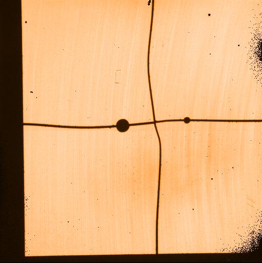
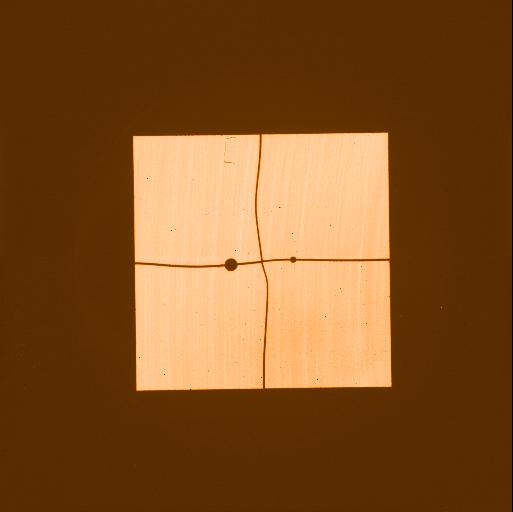
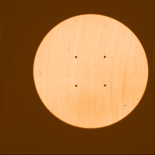
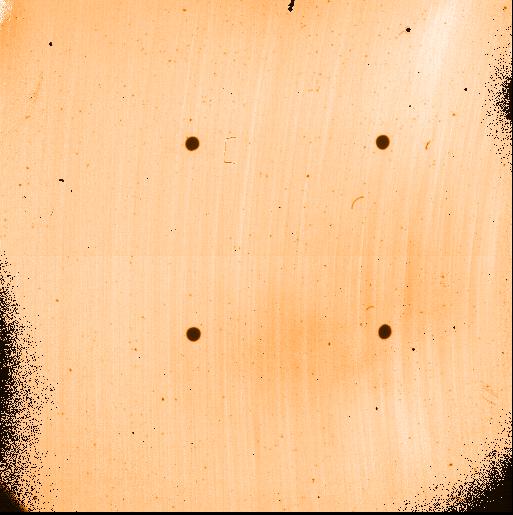
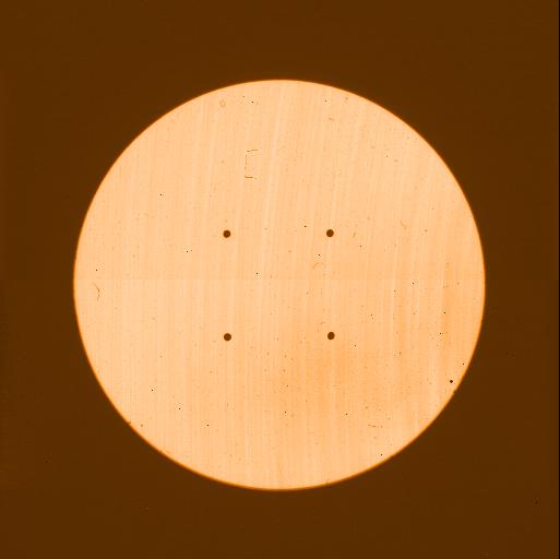
- Classical dark mask (Lyot stop): 2 opaque disks of diameter 0.7 & 1.4".
These masks are held by metallic wires which cross in the middleand create another small mask that is offered under the name C_0.7_1.4. - One semi-transparent mask (C_0.7_sep_10): on a transparentsubstrate over a diameter of 0.7" the transmissivity is reduced to 0.4%(0.3%) for H-band (Ks-band).
Please note that, while in principle it is possible to use the semi-transparentmask with S13 camera, the mis-alignment between the mask and CONICA detector significantly vignets the available field of view, so that the only possiblespot is the lower left one, with some vignetting in the bottom left side ofthe mask. Because of this, the use of the C_0.7_sep_10 with S13 camera is not recommended, except to experienced users.
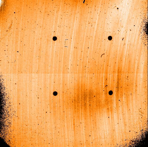
To avoid problems with high sky background, users wishing to observe in theLW range, are recommended to acquire their objects using the SW camera, thenchange to LW in the science template. - Two new four quadrant phase masks, one optimized for the H (4QPM_H) and one for the K band (4QPM_K) are offered as of P80 and replace the old 4QPM optimized to work in K band. These masks reduce the intensity of a source by adding a phase shift of pi to the wavefront. Both masks also include a small Lyot mask 0.15" diameter located in the center, which mitigates the effect of residual jitter. Peak attenuation for the masks is ~100, a gain of ~2 with respect to the old 4QPM. More details below and in the User's manunal.
All filters and cameras can be used. See the user manual for restrictions with the 4QPMs.
4QPM coronagraphy can be used in combination with pupil tracking (VM and SM).
For each mask and objective, 512x (red) and 256x (blue) windowing regions have been drawn on the reference frames, just click on the lins in the table to see how the field of view is affected.
| S13 Objective | S27 Objective | S54 Objective | L27 Objective | L54 Objective |
|---|---|---|---|---|
| C_0.7 | C_0.7 | C_0.7 | C_0.7 | C_0.7 |
| C_1.4 | C_1.4 | C_1.4 | C_1.4 | C_1.4 |
| C_0.7_sep_10 | C_0.7_sep_10 | C_0.7_sep_10 | C_0.7_sep_10 | C_0.7_sep_10 |
| 4QPM_K | 4QPM_K | 4QPM_K | ||
| 4QPM_H | ||||
| AGPM | ||||
| APP_coro | APP_coro |
4QPM Night tests
Report from the commissioning team
AB Dor was observed between 0h39UT and 0h51UT, followed by a reference star (HD 41371)at the same parallactic angle and observed for the same duration.The Right Ascension of the reference is therefore chosen with a difference equal to the observing time(here about 30 arcmin) and at the same Declination (differing by about 1 degree). In these case the orientation of the telescope pupil with respect to the instrument is more or less identical and as a result, static phase aberrations or amplitude effects (like spiders)keep the same orientation in the FOV.
Seeing ranges between 0.66 arcsec and 1.11 arcsec with a median value of 0.90 arcsec.AO correction was good and stable with Ec=45 +/- 5%.
The two stars are very similar: same spectral type K1III and K0III respectively, same IR magnitudes about mK=4.7 and mH=4.9 according to the 2MASS catalogue, and visible magnitudes are close mV=6.93 and 7.1 respectively. We combined 6 images of DIT=1s, NDIT=120.
The reference is used to calibrate the residual pattern in the image of the star andhence the intensity ratio between the 2 images has to be determined. The optimal intensity ratio is found while trying to minimize the residual intensity in the image. Re-centering of the2 images was not necessary. Raw and subtracted images are presented in Figure 1.The companion AB Dor C is clearly visible even on the direct coronagraphic image. Its distance to AB Dor A is measured to be 0.185 +/- 0.005 arcsec.

Fig. 1: Direct (left) and coronagraphic images, raw (middle) andsubtracted (right) of AB Dor. The companion AB Dor C is clearly visible even on the directimage when contrast is numerically enhanced although it is as bright as some other PSFstructures. The field of view is 2.5 arcsec. North is up, East is left.
Figure 2 shows the radial contrast on the coronagraphic image and the detection level once the halo is calibrated with a reference star.The 5 sigma detectability of a point source reaches ΔKs=6.7mag at 0.2 arcsec and ΔKs=9mag at 0.5arcsec
Fig. 2: Radial profile of PSF, raw and subtracted coronagraphic images of AB Dor as observed in the K band with 4QPM_K. The blue linecorresponds to the averaged intensity in the subtracted image while the red line stands for the 5 sigma detection level.