
MIDI Pictorial
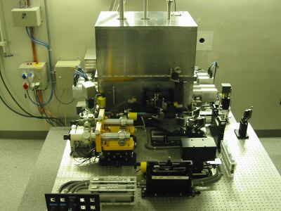
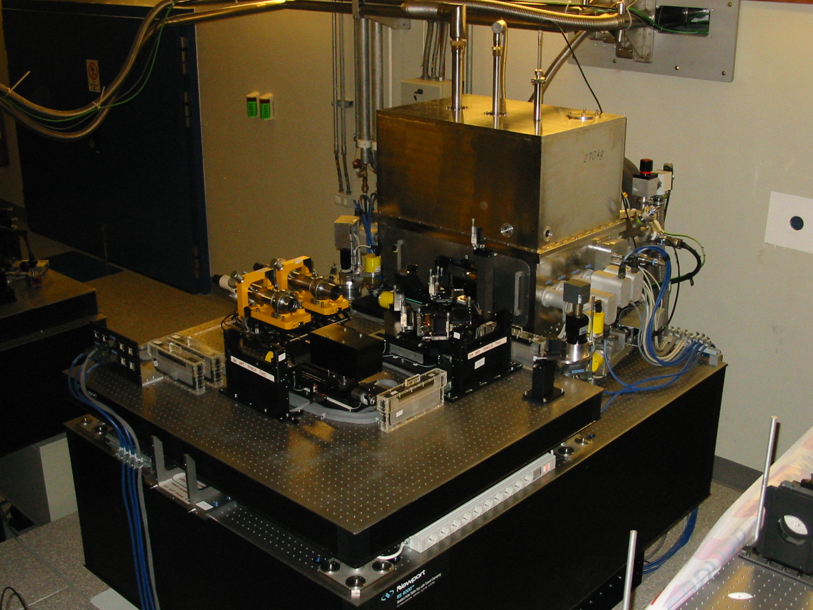
| The MIDI instrument standing in the Interferometric Laboratory of theVLT. Specific features of MIDI like the large cubic cryostat, or the Warm-Optics Breadboard (WOB) are easily noticeable. The total weight of MIDI equipment(table included) in the Interferometric Laboratory is 2.64 tons. |  |
 |
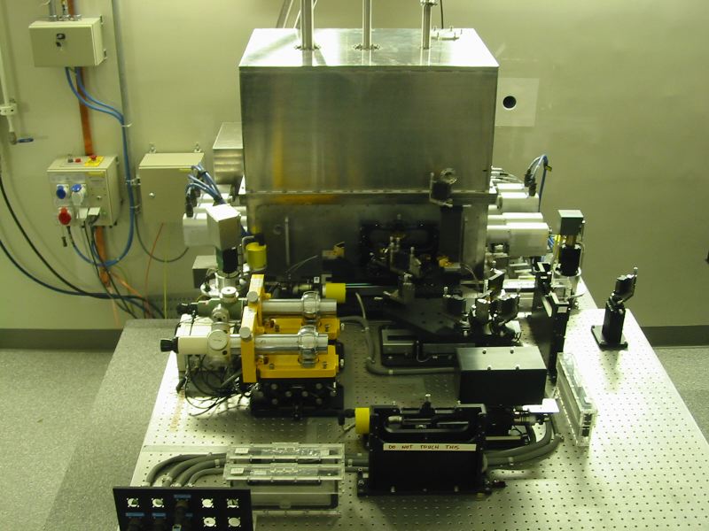
Another view of MIDI showing in detail the WOB. The "blackbody" heaterbox (slided in for detector tests and calibration) is visible at foreground.Behind it are the optics to split the CO2 laser beam (used for tests and coming out from the hole in the wall, on the right side) and to feed the two resulting beams into the MIDI cryostat. Close to the cryostat,are located the two PZT-mounted dihedral mirrors, used for optical path modulation. The alignment equipment (two sighting-telescopes and three reference plates in their Plexiglas cases) is also present on this picture. |
| This unusual view of the open cryostat of MIDI seen from above (photo taken during the integration at MPIA Heidelberg) shows what lies under the hood: the Cold-Optics Bench (COB). The COB is made of anodized aluminium and contain all the elements for beam-combination, spatial and spectral filtering, spectroscopy,imaging. All the mechanisms are driven by "warm" motors located on the sides of the cryostat (see above pictures). The filter-wheel can easily be identified on this image (black disk). The detector is located at the base of the filter-wheel structure. The beam-combiner slider(enclosing the plate for beam-recombination) is located at the right of the filter-wheel on the image. Also visible are the Seiko-Seikiturbo-molecular pump (top right of the image) that creates a 10-5 mBar vacuum required by the cryostat, and (top left of the image) the 2-stage "cold-head". The cold-head is a pump, located at the cold end of the gas-helium closed-cycle cooler (helium supply and return hoses are visible on the image), which "drags" the heat from within the cryostat, allowing to cool the optics inside the cryostat down to 35 K (-238º Celsius) using the first stage. The second stage of the cold-head cools the detector of MIDI down to 4 K (-269º Celsius).The closed-cycle cooler is backed by a tank filled with liquid nitrogen(temp= 77 K or -196º Celsius) located in the upper part of thecryostat (removed on the image). This tank cools down a shield surrounding the MIDI components, and therefore limits the thermal leaks. |
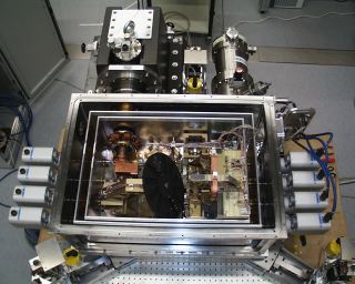 (Courtesy of F. Przygodda, MPIA) |
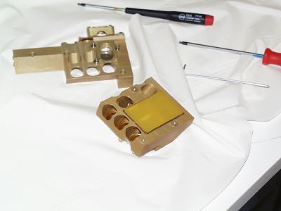 |
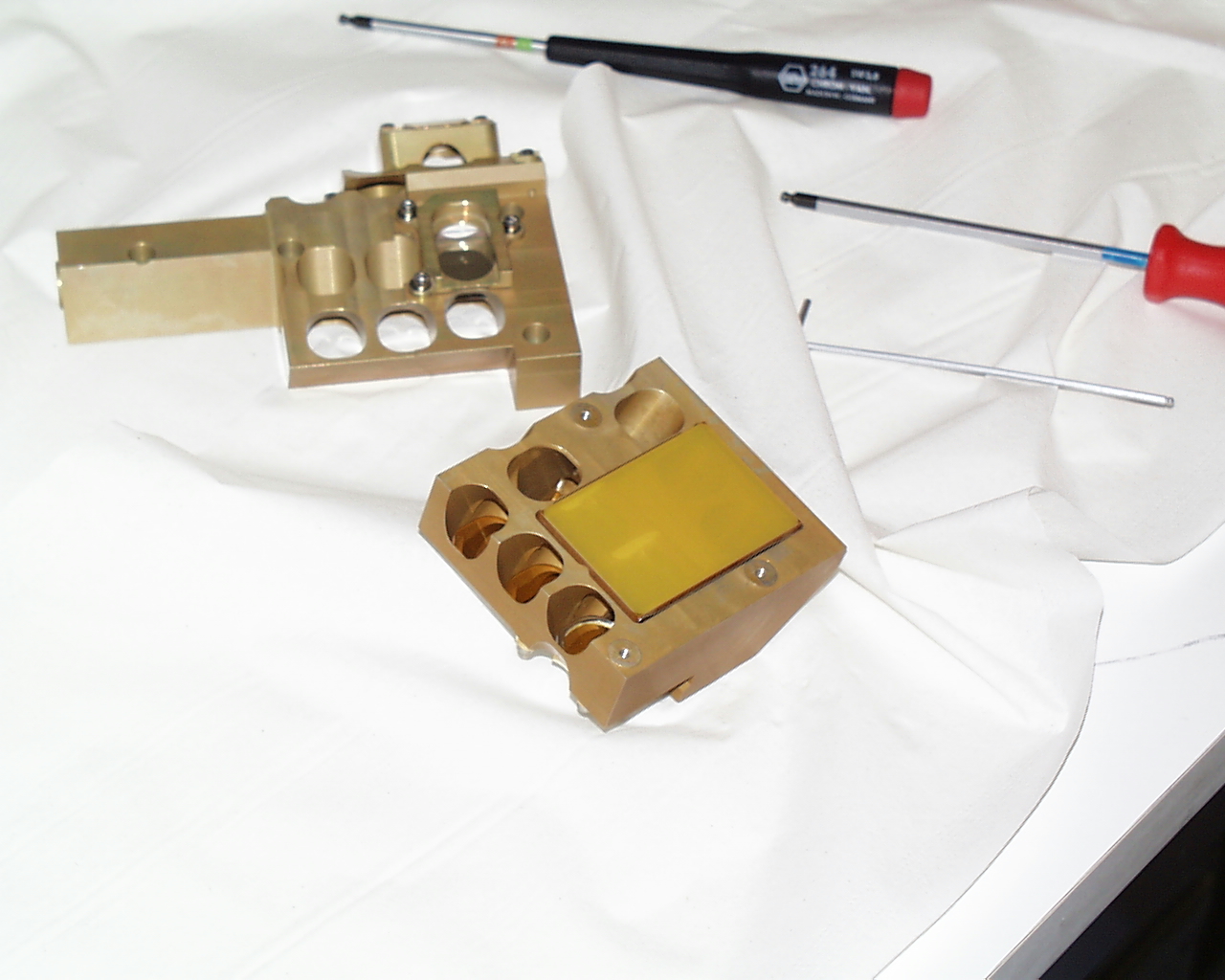
The beam-combiner slider open unveils the heart of MIDI: A zinc-selenide(ZnSe) plate for beam recombination. Half of the plate is coated on one side (not visible on the image) for 50% reflection and 50% transmission of beams on both sides. The uncoated part of the plate is used as a chromatic compensation plate. The same plate is used for both "high-sensitivity"and "photometry" modes of MIDI. The other part of the slider contains the 70/30 beam splitters for photometry. This picture was taken during MIDI integration in Heidelberg. |
| Where the stellar light ends: the detector of MIDI. This 240 x 320pixel Si:As (Impurity Band Conduction) array is noticeable by its fast readout (thanks to 16 parallel channels), providing up to 160 frames per second (in "integrate-then-read" mode). The picture shows the solid-state chip installed in the detector head of MIDI. A part of the control electronics (clock, bias, and pre-amp boards)of the detector is located on a flange of the cryostat. The other part(ADC, DSP-controller, pattern-memory, and fiber-link boards) have been installed in the Combined-Coudé Laboratory, to avoid disturbance of the instrument from heat generation. |
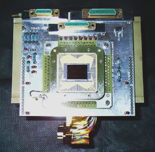 (Courtesy of S. Ligori, MPIA) |
 |
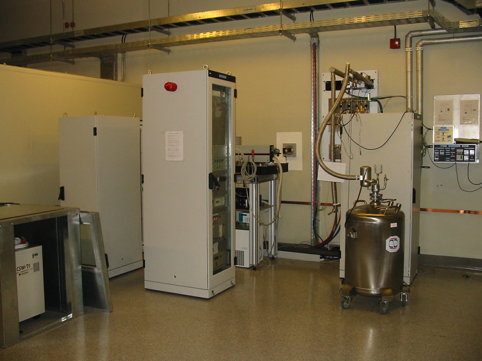
View of the ancillary equipment of MIDI in the Combined-Coudé laboratory of VLT. The three cabinets contain all the electronics to control vacuum, cryogenics, motors, PZTs and detector of MIDI. The CO2test laser (on the table close to the wall) is also installed there. The compressor of the closed-cycle cooler is visible on the left side, in its enclosure with the hatch open. The liquid nitrogen tank to fill the cryostat of MIDI can be seen on the right side. |
| A typical MIDI detector image (life-size), given by the "field"camera mode of MIDI. The two disks correspond to the field-of-view of the two entrance beams (without beam-combiner before the detector), illuminated by the thermal background of the environment(walls of the laboratory). The vertical stripes correspond to the readout channels of the detector, which have slightly different gains,especially at the edge. Substraction by reference image allows to discard these artifacts. | 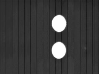 |
 (Courtesy of F. Przygodda, MPIA) |
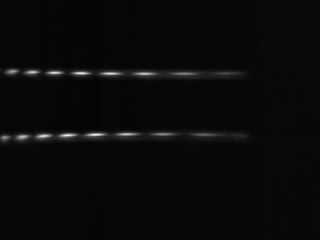
Dispersed fringes (obtained in laboratory with the high-sensitivity beam-combiner and the grism) in the plane of the detector of MIDI. These fringes were acquired after background substraction, with OPD slightly different from zero. The two fringe patterns (one in each interferometric channel) are in phase opposition, due to the structure of the beam-recombiner. |