VLT Nasmyth Adapter-Rotator
Overview
The complete adapter-rotator units comprise two major subsystems:the opto-mechanical part and the control system. The Opto-Mechanicalpart consists of five main sub-components:
- The Large Structure
- The Sensor Arm
- The M4 Unit
- The Folded Nasmyth Focus Device
- The Maintenance and Integration Equipment
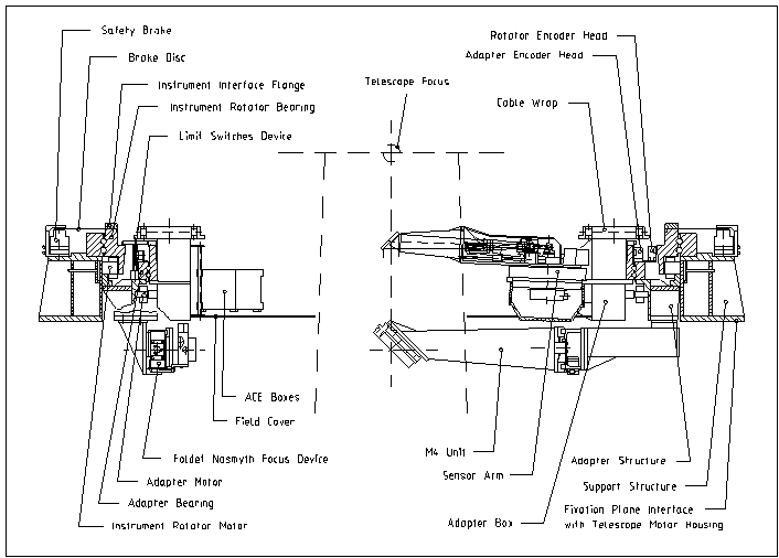
The figure shows the general sectional view of the NasmythAdapter-Rotator indicating the main elements.

The Large Structure
The Large Sctructure is composed of three main sub-components, theSupport Structure, the Instrument Rotator and the Adapter plus somesmaller assemblies (Safety Brake, Limit Switch systems, Cable Wrap,Hoses and Cables, and Nasmyth Connection Box).
The Support Structure is a welded structure which supports theInstrument Rotator and the Adapter. It is fixed on the motor housing.The Instrument Rotator consists of a large flange to which the scientificinstrument is attached. The flange is mounted on a bearing which isdriven by a Drive Unit to allow the instrument to be rotated aroundthe telescope optical axis to follow the rotation of the telescope field.
The Adapter consists of the Adapter Structure, the Adapter Box and theDrive Unit. The Adapter Structure is fixed to the Support Structure andsupports the Adapter Box. Like the Instrument Rotator, the Adapter Boxis supported by a large bearing. The Drive Unit allows the Adapter Boxto be rotated about the telescope optical axis. The Adapter Box, in turn,supports the Sensor Arm described below.
The Cable Wrap transportsCables And Hoses from the Adapter Structure to the Adapter Box and SensorArm.
The Safety Brake prevents motion of the Instrument Rotator when theRotator Drive Unit is not powered.
The Limit Switch Systems controlthe limits of rotation of the Adapter. The Nasmyth Connection Boxserves as a junction point between the fixed cables and hoses comingfrom the CEC with those from the Adapter-Rotator.
The Sensor Arm
The Sensor Arm comprises a Turntable, a Supporting Arm, the SupportingArm Structure, a Focusing Device, a Reference System and an OpticalSystem. The Supporting Arm assembly is attached to the Adapter Boxby means of the Turntable which allows it to rotate about an axis atthe edge of the telescope optical field. At the end of the SupportingArm is a pick-up mirror which directs light from the telescope beam,through the Optical System, to two CCD sensors.
The Focusing Device allows the adjustment of the CCD sensor focusposition.
The Reference System inserts an optical fibre intothe beam for calibration purposes. The combined movements of theSensor Arm and the Adapter Box allow the pick-up mirror to be placedanywhere in the telescope field.
The M4 Unit
The M4 Unit bends the optical beam coming from the telescope to thefolded Nasmyth Focus and Coudé Focus. It is mounted on a linearbearing assembly which moves it into the optical path.
The Folded Nasmyth Focus Device
The Folded Nasmyth Focus Device (FNFD) is located at the folded Nasmythfocus and provides the necessary tools for Coudé Beam alignmentand optical maintenance of the telescope.
The Maintenance and Integration Equipment
The component comprises a number of assemblies which are used for theassembly, alignment, handling maintenance and tests.
Table of Content
- The VLT 8.2-m Unit Telescope
- VLT Environmental Specifications
- The VLT primary mirrors
- The VLT Primary Mirror Cooling System
- The Secondary Mirror, M2 Unit
- The M1 Cell and M3 Tower
- The VLT Active Optics System
- The VLT Adapter-Rotators
- VLT Cassegrain Adapter-Rotators
- VLT Nasmyth Adapter-Rotator
- Very Large Telescope Enclosure
- VLT Technical CCD System
- Coating Unit
- Sky Accessibility
- UT Performance
