The VLT Active Optics System
Overview
Due to the low ratio between their thickness and their diameter, the VLT primary mirrors will be rather flexible and sensitive to various disturbances, requiring permanent control of their optical shape.
Active optics consists in applying controlled forces to the primary mirror and in moving the secondary mirror in order to cancel out the errors. The scheme was developed by ESO for the 3.5-m New Technology Telescope (NTT) and is now applied to the VLT. The system must essentially compensate fors tatic or slowly varying deformations such as manufacturing errors, thermal effects, low frequency components of wind buffeting, telescope inclination,... It is also used when changing between Cassegrain and Nasmyth foci.
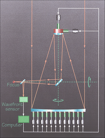
A schematic view of the system is shown below.

(Drawing by Ed Janssen, ESO)
Description
The different elements of the active optics system of the VLT are the primary mirror, with its active support system located within the M1 Cell structure, the M2 unit, the CCD Shack-Hartmann wavefront sensor (WFS) located in the sensor arm of the adapter, and the computer analysing the wavefront sensor data. There are three modes of operation, that are described below
Baseline
The active optics baseline operation is the correction of wavefront aberrations generated by the optics of the telescope and by slowly varying temperature inhomogeneities in or near the building.The corrections are based on an image analysis.
The active optics system constantly monitors the optical quality of the image using an offset reference star as it is picked up in the field by the wavefront sensor CCD in the adapter sensor arm.The same offset star is also used by the acquisition and autoguiding CCD.
The system controls the relative position and the shape of the optical elements. The primary mirror shape can be actively controlled by varying the force pattern applied by means of its support system. The latter consists of 150 computer controlled axial actuators, applying a distribution of forces at the back of the mirror.
Periodically the image analyzer calculates the deviation of the image from the best quality. The image analysis typically requires about 30 seconds (1/30 Hz) in order to integrate out the effect of atmospheric seeing. The computer decomposes the deviation into single optical contributions (defocus, astigmatism, coma etc...) and calculates the force correction which each active element has to perform to achievethe optimal quality. The set of 150 correction forces, one for each axial actuator, is computed and transmitted to the local control ofthe M1 Cell-M3 Tower for execution. The focus and coma terms are corrected by displacements of the secondary mirror.
Fast corrections
The feedback scheme is the same as above but here the maximum frequency for fast corrections is 1 Hz. These shorter integration times reduce the signal to noise ratio of measurements and affect both the sky coverage (requirement of brighter guide stars in the field) and the number of aberrations which can be corrected(only the lowest spatial frequency ones).
Open loop corrections
This mode does not use feedback information from the image analyser.The open loop mode is used in the absence of any sufficiently bright guide star, or in the case of image analysis failure, or as initialization for baseline operation after a new telescope preset. For this type of operation accurately predicted forces on M1 (dependent on telescope tube inclination) and predicted positions (dependent also on temperature) are required.
References
More technical information on the principles of active optics can be obtained in the following publications:
R. Wilson, F. Franza, L. Noethe, Journal of Modern Optics, vol. 34/4, 1987, p. 485L. Noethe et al., Journal of Modern Optics, vol. 35/9, 1988, p. 1427
Table of Content
- The VLT 8.2-m Unit Telescope
- VLT Environmental Specifications
- The VLT primary mirrors
- The VLT Primary Mirror Cooling System
- The Secondary Mirror, M2 Unit
- The M1 Cell and M3 Tower
- The VLT Active Optics System
- The VLT Adapter-Rotators
- VLT Cassegrain Adapter-Rotators
- VLT Nasmyth Adapter-Rotator
- Very Large Telescope Enclosure
- VLT Technical CCD System
- Coating Unit
- Sky Accessibility
- UT Performance
