
The CCD processes.
The CCD software has a workstation part (commonly known as DCS - Detector Control Software) and an LCU part that actually does most of the work. Additional software runs inside the ACE controllers but this is extremely well shielded from the control system.
On the workstation ccdconCI_susi (for example) provides the main interface to the CCD software. The same basic task comes in different flavours for each CCD being controlled, independently of whether it is a scientific CCD or a technical one.
On the LCU the ip and it tasks also run (Image Processing and Image Transfer). The CCD software transfers the image from the LCU to the workstation when the image processing is finished. Because the image must always be presented to the user in a fixed orientation in the case of a scientific CCD where the readout port maybe on the opposite side to the pixel nominated as (1,1) the whole image may be readout into the LCU before it is transferred to the workstation. In this case the CCD software in the LCU flips the image in memory so as to present it to the user with pixel (1,1) at the bottom left.
Image processing includes CCD provided functions such as centroiding (used by the auto guiding) or minimum, maximum calculation. When these are enabled (see below for info on the CCD standalone panel) the image has to be completely within the LCU memory before transfer.
The standalone panel.
The CCD software starts up in many guises. The most common direct mechanism for driving the CCDs is via the stand alone panels. The standalone panels for every camera may be started by selecting the option from the menu (on vue). When the panel is started, the CCD software is also started at the same time. However, if the LCU software has not been started then the command START-UP needs to be issued from the panel.
The panel that is started has a variety of sub areas.
The General Area
Here you can see which camera the system is attached to and its state. You can switch the camera "on" or "off" and call up the engineering interface to the CCD (making available the enabling/disabling of the scans as well as rebooting the LCU)
WARNING!
Changing the configuration of the CCD (e.g. the gain, readout port, clock pattern) which can be done by calling up the configuration panel can be extremely dangerous to your data and the operations of the telescope. DO NOT UNDERTAKE THIS TASK LIGHTLY!
The Set-up Area
Here you can choose whether to store a file with each exposure as well as what it is to be called. When the CCD SW finds a file of the same name (say name.fits) then the new file created will be name0.fits and name1.fits after that and so on.
You may choose to transfer only one in a series of images, whether you want to display the images in the RTD. You can choose to repeat an exposure a number of times or even indefinitely.
To change the window parameters click on the windowing check box. If this is not selected then the full window will be used. When the windowing area is selected you can specify the start pixel and the width of the window.
In the set-up area you will also find the option for real time processing. Here you can specify for the LCU CCD software to perform some processing of the images as they arrive BEFORE they are transferred to the workstation. The default processing options are centroiding (centre of gravity calculation on the full window) and calculation of min, max. values. Note that if you select this option the CCD SW will wait for the whole image to be in the LCU before transferring it to the workstation. Otherwise you get the data displayed on the RTD as they are readout. As mentioned above you will also have to wait until the end of the readout if the readout port selected on the chip is not such that the first pixel readout is at the bottom left of the image.
You may also select a user function to be executed within the CCD SW. A couple of image processing (gaussian fitting) user functions have been coded but not as yet released.
The Control Area
The control area is context sensitive. Therefore buttons will only become available when it makes sense. You may switch this feature off from the general area. When integrating in a loop, whether continuous or finite, the `Stop loop' button will stop the current loop after the exposure taking place is over. For a long integration will will need to `Abort' as well.
Note that, the TCCDs are frame transfer CCDs without a shutter and therefore it is meaningless to `Pause' an integration.
The Status Area
Here the parameters of the observation are displayed. You will need to ckick on the appropriate check button to see the values. In any case the status of the integration and the loop counter are always displayed. In the case of a failure of the system the message is displayed in the exposure and system status sub areas.
Note that when you abort an exposure the system status will display a failure state.
The parameters generated by the image processing are also displayed here.
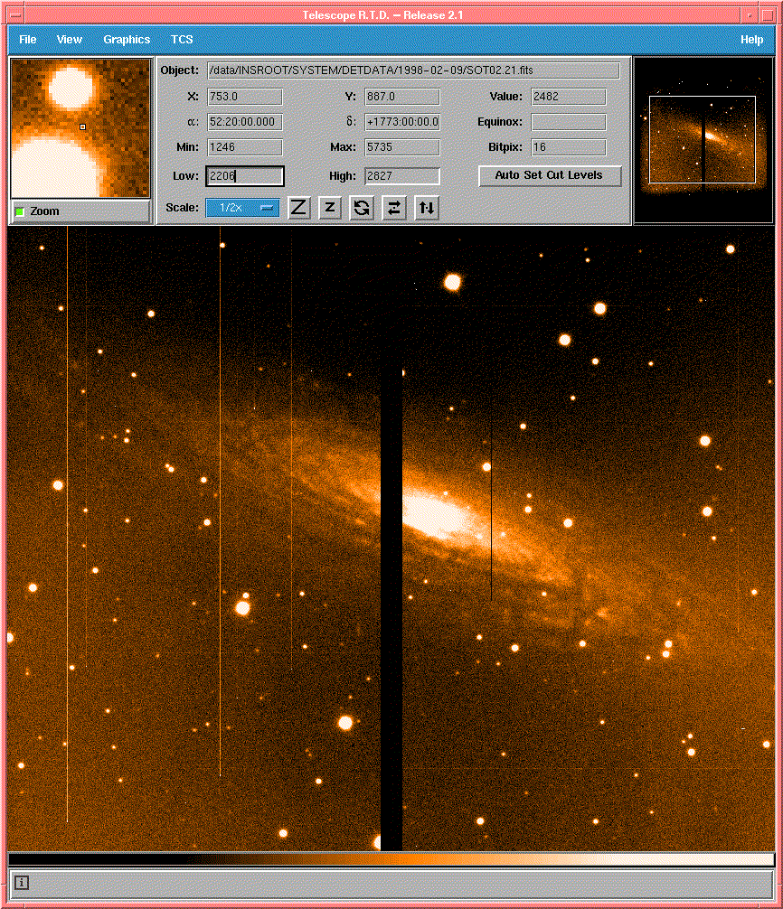
Real Time Display (RTD)
The Real Time Display facility is used for the readout of all CCDs. This is a very versatile tool which will in time provide all functionality presently found in the MIDAS used for displaying images from the detectors. In addition to using the RTD to view the data as taken by the CCDs you may also use it to open any FITS file, display its header and print it.
The RTD is started by selecting the option from the INS menu (on vue).
The way the RTD works is using a process on the workstation called the rtdServer. The rtdServer is instructed to listen to a specific camera by the start-up script. However, you may change the camera any specific RTD is displaying using the Set Camera command which lives under the `TCS' menu.
On the Set Camera window, you can specify the camera you wish to be using. On wa5tcs we have the cameras: ccdaga, ccdagb, ccdiaa, ccdiab, ccdiqa, ccdiqb and ccdsv. On wemmi we have cameras lemcs, lemcb and lemcr.
Using the attach/detach camera you may choose to look at the readout from the selected camera. The data are transferred to the workstation memory and are scaled and displayed by the RTD. The widget provides a large number of scaling and colour options as well as real-time updates on the real pixel values and cuts across the image. Under the `view' menu you will find various options. Best to try them out. From the RTD you may also save the displayed image as a FITS file. However, this image is for display purposes only and although all the data values will be correct the FITS header will be created by the RTD with the information that was attached to the image by the CCD software and no information about the instrument or telescope will be present.
The `cuts' and `Pixel Table...' options will produce new windows where the information will automatically be updated when a new frame arrives.
The line displayed in the `cuts' is drawn by the user and as mentioned above the cuts will be updated in real time when the next image arrives.
The same applies to the Pixel Table Display, which can be display a variety of numbers of rows and columns. The pixels displayed move with the cursor and the one marked in red is the one directly under the cursor. For fine tuning you may move the cursor with the arrow keys on the keyboard.
The values displayed in the pixel table are real data values and NOT displayed image values (i.e. you get the full dynamic range of the CCD).
For some applications another option exists under the `TCS' menu, selecting `Pick Reference Star'. Here following a change (using the scroll bar) of the sample size you can click on any star in the field and get various parameters for the star.
During the `pick object' the RTD detaches from the camera and reattached as soon as you have picked. The sub window, as well as the main window, will then update as per normal.
You can run as many RTDs as you like on the same camera. So if you are on wemmi and wish to see what the autoguider is doing you need to log on to wa5tcs start the tcscam (on vue menu) and attach to the camera. Your display will not be updated as often as the one on wa5tcs.