PLC Libraries
Common Attributes and Functionality
Note
ESO PLC libraries have to be installed in the TwinCAT development environment before they can be used in projects.
Library content
For each function, e.g. lamp, shutter, motor, etc, the corresponding PLC library delivers:
A function block (FB) for function control, e.g. FB_LAMP. Note that some libraries deliver more than one FB, e.g. motor.library.
A function block for the HW simulator, e.g. FB_SIM_LAMP
A template GUI, e.g. GUI_TEMPLATE_LAMP
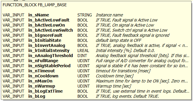
Input parameters
In most cases, apart from the Motor library, the configuration parameters can be given in the execution part, i.e. the FB call. This way some configuration parameters that are known that will not change, e.g. active low, timeouts, etc, can be ‘hard-coded’. Input parameters have the prefix in_. There is a mandatory input parameter called ‘in_sName’ that sets the name of the device. On PLC reboot these parameters will be set in the device configuration. However, the configuration defined in the Device Manager will overwrite the device configuration on INIT. This way, by giving input parameters the number of configuration parameters can be reduced or completely avoided but still with the flexibility of correcting any configuration parameter by the Device Manager without modifying the PLC code.
Example:
Lamp1(in_sName:='Lamp1', in_bActiveLowFault:=TRUE);
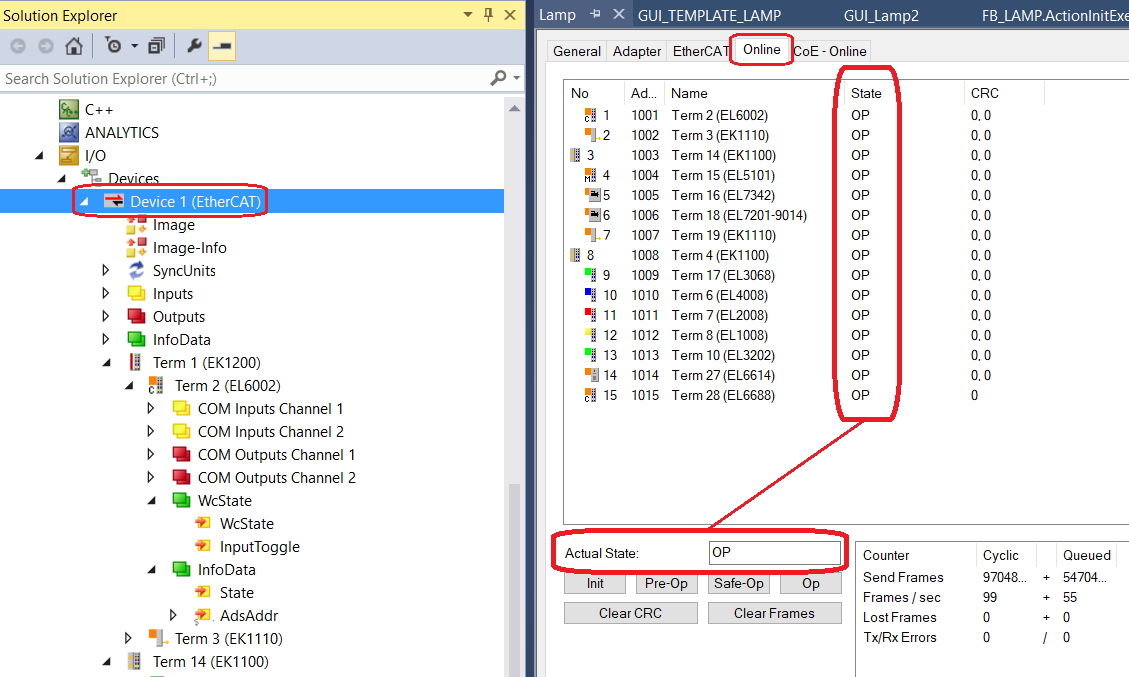
EtherCAT Operational State and FB Input variable i_nCouplerState
In order for the EtherCAT system to operate, it has to be in OPERATIONAL state with its corresponding value equal to 8. Any value other than 8 indicates that the system is not OPERATIONAL. The EtherCAT system is OPERATIONAL only if all I/O terminals in the system are OPERATIONAL. The figure below shows an OPERATIONAL EtherCAT system and the individual state of each I/O terminal in the system.
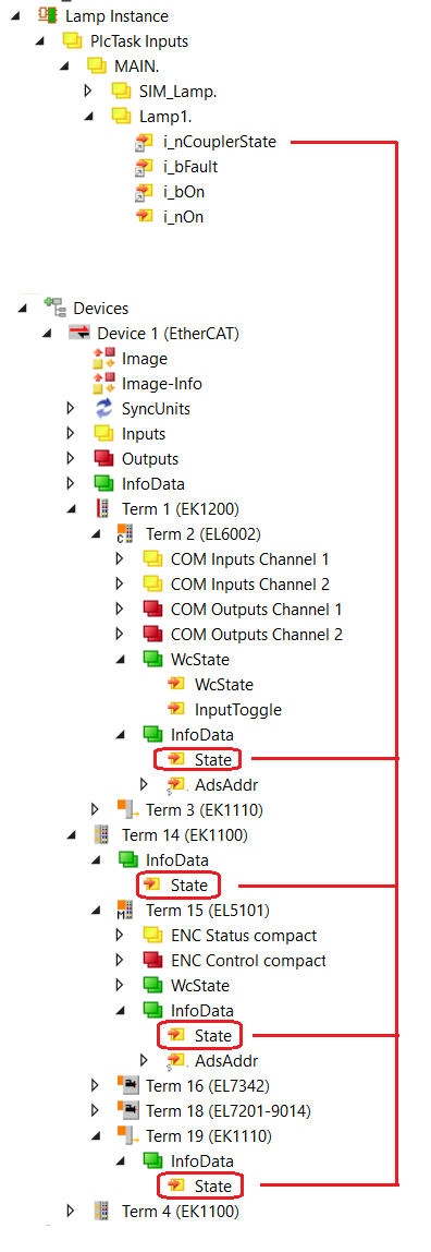
Each FB that controls HW has got an input variable called i_nCouplerState. This variable is used to monitor the state of the EtherCAT system. The variable has to be linked (mapped) to the State variable, found in the InfoData structure of the I/O terminal, that indicates its operational state. Normally, the variable is linked to the State of the EK1100 coupler that holds the I/O termials used by the FB. That’s why the variable is called i_nCouplerState. However, the State variable of any other I/O terminal, e.g. EL2008, could also be used for that purpose. The figure below shows some possible mapping options for i_nCouplerState.
Interface with Device Manager
Device managers control the PLC device exclusively via RPC methods. There are a number of mandatory RPC methods that are common to all PLC devices. They are related to device state changes and logging. Each library, in addition to the function specific RPC methods, delivers the following RPCs:
RPC_Init()
RPC_Enable()
RPC_Disable()
RPC_SetDebug()
RPC_SetLog()
RPC_Stop()
RPC_Reset()
In order to have RPC methods visible in the OPC UA address space, each declaration of an FB has to be coupled with a pragma statement {attribute ‘OPC.UA.DA’:=’1’}.
Example:
{attribute 'OPC.UA.DA':='1'}
Lamp1: FB_LAMP;

{attribute 'OPC.UA.DA':='1'}
Lamp2: FB_LAMP;
Operational Logs at PLC Level
Device operations are by default logged on the PLC. The screenshot below shows how to open TwinCAT Logged Events Window.
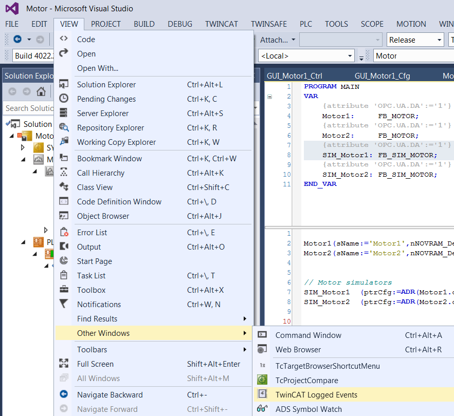
RPC methods RPC_SetDebug() and RPC_SetLog() are used to control the amount of logging information. If provided, debugging logs should be activated only for troubleshooting purpose since they could generate large amount of data.
In order to see the logs, the window has to be refreshed as shown below:

PLC simulators
In most cases the library includes a HW simulator that is linked to the device FB and gives quite realistic response. This way it is possible at a very early stage of the project to test Device Managers with a PLC. The device manager is not aware of the simulation at the PLC level and ‘believes’ that it communicates with a real HW.
Note
It is important to note that the PLC application, i.e. program MAIN, has to be modified in order to use simulators. In addition to the inclusion of a device simulator instance in MAIN, the device I/O variables have to be linked to the corresponding simulator I/O signals rather than to the real I/O.
HW simulators capture device INIT event and adjust their internal configuration ensuring that the device will work properly after the initialisation. For example, the simulator response time will be shorter than the device timeout.
Simulators provide RPC calls that are used to modify their response in order to test failure conditions of the device driver. For example, the Lamp RPC_SetFault() method can be used to set the fault signal of the lamp.
C++ Modules
For some PLC devices, additional software developed in C++ might be needed. TwinCAT enables the implementation of modules in C++ that run inside the TwinCAT real-time kernel. These modules communicate with the PLC via normal I/O mapping (Communication between C++ modules and PLC).
The FCF provides some C++ modules for the computation of the field rotation in the CCS simulator library.
The installation of the C++ module must be done on every computer used to build and download PLC projects that include projects using C++ modules. These modules have been already compiled and published by ESO and archived here.
Note
Visualisation and recompilation of the C++ module sources is only possible using commercial versions of Visual Studio (VS), e.g. VS Professional. However, C++ modules can be imported into the standard TwinCAT environment without the need to recompile them.
The procedure describing how to import modules into TwinCAT is available on Beckhoff website: (Importing C++ modules).
Note
In IFW version 4, C++ modules are not required for tracking devices since the information will be provided by CCS (deterministic network) instead of being computed locally. However, the ccssim library contains these modules for providing simulation capabilities when CCS would not be available.
Tracking
Tracking controllers are motorized devices which update continuously the position of one or more motor axes as a function of the telescope coordinates, UTC time or variations of the temperature. Tracking controllers share some common characteristics that are described below.
They support at least two modes of operations: one where motor axes are stationary and another one for tracking. In both cases the motor axes are moving in position mode.
They may require an additional TwinCAT runtime license in case of using a C++ module. The required TwinCAT license is the C++ runtime.
They may require a connection to the ELT time synchronization system to maximize tracking accuracy of the motor axes. A dedicated terminal (EL6688) is needed to connect to the ELT time synchronization system.
The tracking position control loop is handled at lower level (PLC) by dedicated function blocks. The period of the position control loop is configurable and does not depend on the PLC cycle.
State Machine of Tracking Devices
The generic state machine of tracking devices is shown below. The main operational states are Standstill, Moving, Presetting and Tracking.
Note
The following State Machine is common to all tracking devices, e.g. Derotators, ADCs, etc.
Note
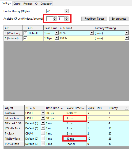
Important note: The cycle time of the task (e.g. PlcTask) that executes an instance of a tracking function, i.e. FB_MA_ADC, FB_MA_DROT, etc, must be the same or longer than the cycle time of the NC-Task 1 SAF task. In other words, the instance of these FBs must not be executed faster than the NC-Task 1 SAF task. Otherwise, there could be some synchronization problems when exiting tracking mode.
Note that the default cycle time of the NC-Task 1 SAF task is 2 ms. Therefore, if the PlcTask cycle time is for example set to 1 ms, the NC-Task 1 SAF task cycle time has to be set to the same value.
Automatic TwinCAT Project Creation
A Windows utility called MakeTcProject.exe is provided for automatic creation of TwinCAT projects with a selectable number of all available controllers. The utility generates a fully operational project that includes the selected number of devices/controllers and their simulators, i.e. every device is simulated at PLC level.
This can be very useful at very early stages of projects when HW is still not available, since it makes it possible to test the complete control system as if the HW were present.
The utility is explained in detail in Creating PLC Applications with MakeTcProject Utility.
Lamp Library (lamp.library)
FB_LAMP is the TwinCAT PLC Function Block for the low level control of the standard lamp device with or without intensity control.
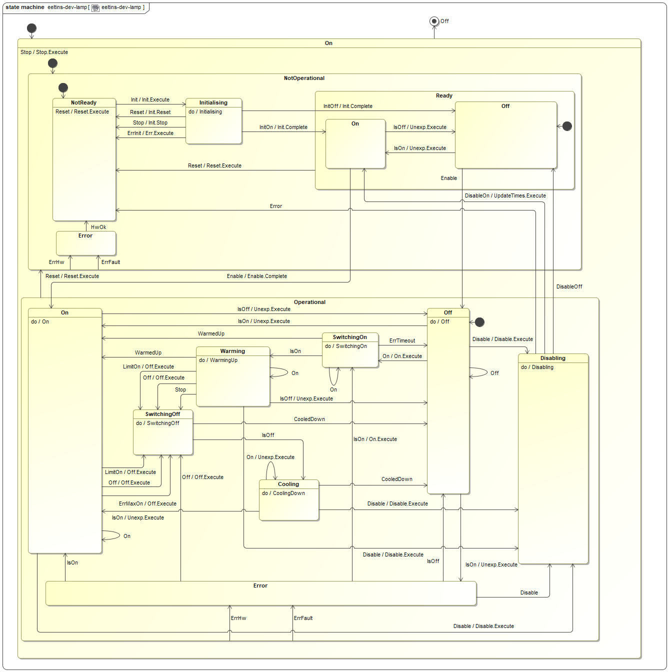
State Machine
The state machine of the lamp controller is shown below. The main operational states are On, Off Warming and Cooling.
Input parameters
Signal Mapping
The figure below shows the TwinCAT view of the FB_LAMP I/O variables that are available for mapping to physical signals, i.e. ports of I/O terminals.
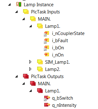
Example of FB_LAMP input/output signals.
The table below describes each mapping variable.
Variable |
Port Type |
Optional Mapping |
Description |
|---|---|---|---|
i_nCouplerState |
UINT |
No |
Mapped to the ‘state’ of the coupler that hosts I/O terminals. If the terminals span over more than one coupler, it is recommended to select the ‘state’ of the last coupler that hosts a lamp signal. |
i_bFault |
Digital In |
Yes |
Does not have to be mapped if ‘fault’ signal is ignored, i.e. does not exist. |
i_bOn |
Digital In |
No |
Mapped to the Lamp status (ON/OFF) digital input signal. |
i_nOn |
Analog In |
Yes |
Analog feedback signal. Has to be mapped only if analog feedback is used. |
q_bSwitch |
Digital Out |
No |
Mapped to the Lamp control digital output signal. |
q_nIntensity |
Analog Out |
Yes |
Mapped to the Lamp intensity analog output signal (if exists). |
GUI Template
The Lamp Library provides a template GUI to control instances of FB_LAMP. Applications can easily deploy an instance of this GUI by setting the GUI reference to the particular instance of FB_LAMP, as shown below.
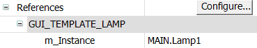
Instantiation of GUI_TEMPLATE_LAMP for Lamp1
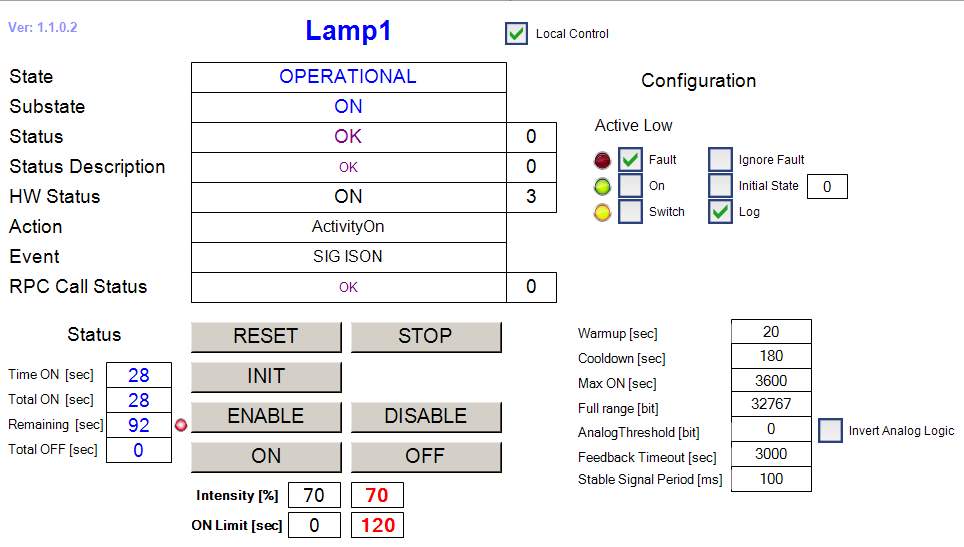
FB_LAMP HMI for Local Control.
Lamp specific RPC Methods
RPC_Off() Turn lamp OFF
RPC_On() Turn lamp ON
Lamp Simulator
The function block FB_SIM_LAMP implements the lamp simulator on the PLC. The simulator has the address of the lamp instance as the only input parameter. The following code shows how the simulator is declared and executed:
Declaration:
{attribute 'OPC.UA.DA':='1'}

Lamp1: FB_LAMP; // Simulated lamp

{attribute 'OPC.UA.DA':='1'}

SIM_Lamp: FB_SIM_LAMP; // Lamp simulator
Execution:
Lamp1(in_sName:='Lamp1', in_bActiveLowFault:=TRUE);

SIM_Lamp(ptrDev:=ADR(Lamp1));
Simulator Mapping

Simulator RPC Methods

Shutter Library (shutter.library)
FB_SHUTTER is the TwinCAT PLC Function Block for the low level control of the standard shutter device.
State Machine
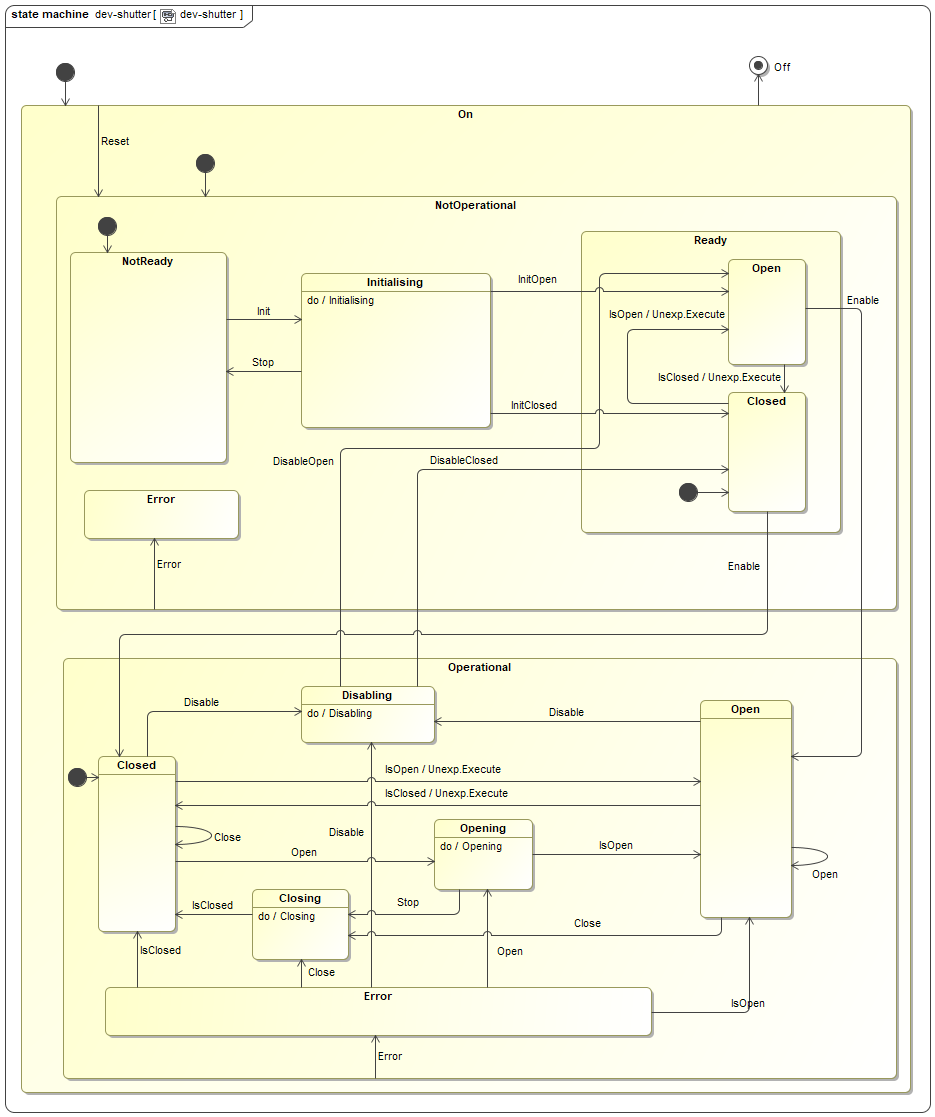
The state machine of the shutter controller is shown below. The main operational states are Open, Closed, Opening and Closing.
Input parameters
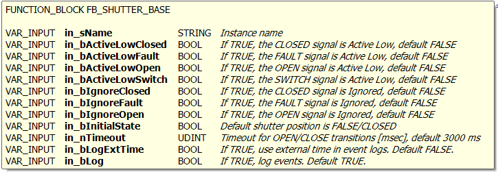
Signal Mapping
The figure below shows the TwinCAT view of the FB_SHUTTER I/O variables that are available for mapping to physical signals, i.e. ports of I/O terminals.
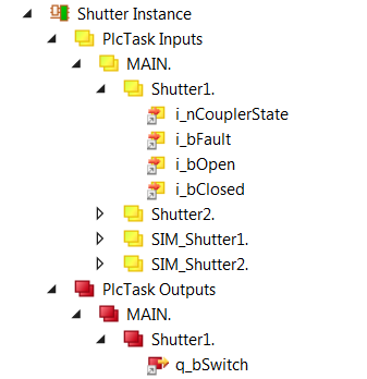
Figure 4: Example of FB_SHUTTER input/output signals.
The table below describes each mapping variable.
Variable |
Port Type |
Optional |
Description |
|---|---|---|---|
i_nCouplerState |
UINT |
No |
Mapped to the ‘state’ of the coupler that hosts I/O terminals. If the terminals span over more than one coupler, it is recommended to select the ‘state’ of the last coupler that hosts a shutter signal. |
i_bFault |
Digital In |
Yes |
Does not have to be mapped if ‘fault’ signal is ignored, i.e. does not exist. |
i_bOpen |
Digital IN |
No |
Mapped to the Shutter ‘open’ digital input signal. |
i_bClosed |
Digital IN |
No |
Mapped to the Shutter ‘closed’ digital input signal. |
q_bSwitch |
Digital Out |
No |
Mapped to the Shutter control digital output signal. |
GUI Template
The Shutter Library provides a template GUI to control instances of FB_SHUTTER. Applications can easily deploy an instance of this GUI by setting the GUI reference to the particular instance of FB_SHUTTER, as shown below.
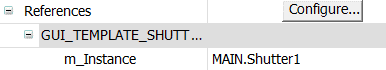
Figure 5: Instantiation of GUI_TEMPLATE_SHUTTER for Shutter1
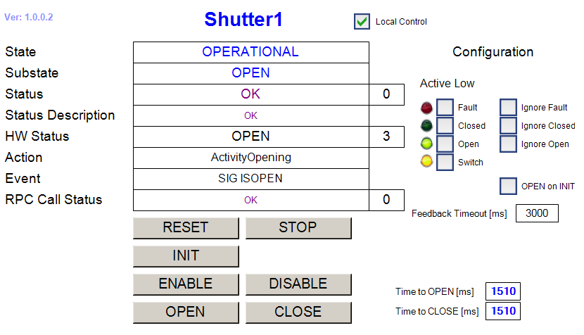
Figure 6: FB_SHUTTER HMI for Local Control.
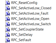
Shutter specific RPC Methods
RPC_Close() Close shutter
RPC_Open() Open Shutter
Shutter Simulator
The function block FB_SIM_SHUTTER implements the shutter simulator on the PLC. The simulator has the address of the shutter instance as the only input parameter. The following code shows how the simulator is declared and executed:
Declaration:
{attribute 'OPC.UA.DA':='1'}

Shutter1: FB_SHUTTER;

{attribute 'OPC.UA.DA':='1'}

SIM_Shutter1: FB_SIM_SHUTTER;
Execution:
Shutter1(in_sName:='Shutter1', in_bActiveLowOpen:=TRUE, in_bActiveLowClosed:=TRUE);

SIM_Shutter1(ptrDev := ADR(Shutter1));
Simulator Mapping

Simulator RPC Methods
Time Library (timer.library)
FB_TIME is the ESO PLC Function Block that provides time services to other components running within the PLC, e.g. computation of absolute time. This FB delivers the time by combining an external offset together with the time delivered by the EtherCAT DC clock. This offset may come from different sources: PTP, NTP or a simulated one.
Note
The FB_TIME in FCF version 4.0 supports NTP. NTP is now provided as part of the TwinCAT Corrected Timestamps. The NTP client inside the TwinCAT is available only in build 4024 or above. To use NTP in the FB_TIME requires to have the NTP added to the project.
Input parameters
The FB_TIME does not have input parameters.
Signal Mapping using EL6688 terminal
The FB_TIME defines a number of mappings that are needed to do the correct computation of the time. Most of these mappings come from the EL6688 terminal. If this terminal is not available in the HW configuration, the FB_TIME could still be used using NTP or simulating a particular time in the PLC.
The table below describes each mapping variable.
Variable |
Port Type |
Optional Mapping |
Description |
|---|---|---|---|
i_inTime |
ULINT |
No |
Mapped to the EL6688 internal time stamp |
i_exTime |
ULINT |
No |
Mapped to the EL6688 external time stamp |
i_dc2TcOffset |
LINT |
No |
Mapped to the EtherCAT Dc2TcOffet |
i_dc2ExtOffset |
LINT |
Yes |
Mapped to the EtherCAT Dc2ExtOffset |
i_extDevNotConnected |
BOOL |
No |
Mapped to the EL6688 External device not connected |
i_syncMode |
UINT |
Yes |
Mapped to the EL6688 Sync mode |
i_AdsAddr |
AMSADDR |
No |
Mapped to the EL6688 ADS address |
q_timeInfo |
T_TIME_INFO |
Yes |
Delivers the actual absolute time (DC) and mode |
Signal Mapping using NTP
Warning
The precision provided by NTP might be not good enough for tracking axes therefore it is recommended to use PTP for those cases.
When using FB_TIME together with NTP, the source of the time offset comes from the TcNtpExternalProvider module that should be configured in the project prior to use the FB_TIME. For more details, refer to the TwinCAT documentation.
Once the TcNtpExternalProvider has been added to the project, it shall be configured by defining the server name, IP and port.
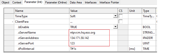
TcNtpExternalProvider: Sample configuration.
The FB_TIME defines some specifics parameters for NTP. The table below describes each mapping variable.
Variable |
Port Type |
Optional Mapping |
Description |
|---|---|---|---|
i_exNtpExtTime |
LINT |
No |
Mapped to the NTP external time |
i_exNtpSysTime |
LINT |
No |
Mapped to the NTP system time |
i_exNtpExtOffset |
LINT |
No |
Mapped to the NTP offset time |
i_NtpConnected |
BOOL |
No |
Mapped to the NTP diagnostic flag |
i_exNtpSynchronized |
BOOL |
Yes |
Mapped to the NT{ diagnostic flag |
q_timeInfo |
T_TIME_INFO |
Yes |
Delivers the actual absolute time (DC) and mode |
The mapping between the NTP and the FB_TIME instance is shown in the folling figure:
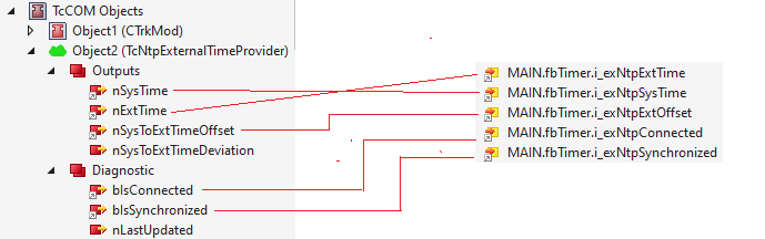
FB_TIME: NTP mapping.
GUI Template
As for other PLC libraries, the timer.library provides a template GUI GUI_TEMPLATE_TIME for control of FB_TIME instances. Applications can easily deploy an instance of this GUI by setting the GUI references to the particular instance of FB_TIME and its name.
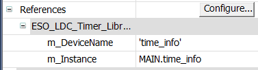
Instantiation of GUI_TEMPLATE_TIME for time_info instance
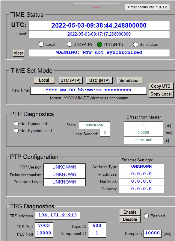
FB_TIME HMI for Local Control.
The user has a choice of three time signals:
Time Signal |
Description |
|---|---|
UTC(PTP) |
Time signal coming from the IEEE1588 PTP server. This is the default time signal. |
UTC(NTP) |
Time signal coming from the TC NTP Client. |
Local |
Local time of the Beckhoff IPC. |
Simulated |
Simulated time. This is the perfect tool for testing SW for specific date and time. |
The GUI instance shown on the screenshot above, the time is obtained from the TwinCAT NTP client. In case it would be needed, the time can be also simulated.
The two buttons Copy UTC and Copy Local are used to copy UTC or Local time string into the entry field for simulated time, avoiding unnecessary typing.
In UTC mode, if the time signal gets lost, the time will automatically switch to Local mode.
Time specific RPC Methods
RPC_GetMode() Get actual time mode: Local, UTC or Simulation.
RPC_SetMode() Set new time mode (Local, UTC or Simulation).
RPC_GetUTC() Obtain the actual absolute time and mode.
RPC_SetTime(string) Set a user defined time (only works in Simulation mode).
Note
By downloading a new new version of the PLC project, the FB_TIME might switch automatically to local time. To avoid this, applications shall force the setting to be NTP time within the projects (SetMode(E_TIME_MODE.UTC_NTP)).
Motor Library (motor.library)
Note
Important note: The cycle time of the task (e.g. PlcTask) that executes an instance of any FB delivered in motor.library that controls motors, i.e. FB_MOTOR, FB_MA_ADC, FB_MA_DROT, etc, must be the same or longer than the cycle time of the NC-Task 1 SAF task. In other words, the instance of these FBs must not be executed faster than the NC-Task 1 SAF task. Otherwise, there could be some synchronization problems, in particular when exiting tracking mode.
Note that the default cycle time of the NC-Task 1 SAF task is 2 ms. Therefore, if for example the PlcTask cycle time is set to 1 ms, the NC-Task 1 SAF task cycle time has to be set to the same value.
FB_MOTOR is the TwinCAT PLC Function Block used to operate motors. The library is based on the Beckhoff MC Library that is in turn PLCOpen MC compliant. This means that it should be possible to use the library for control of any type of motor, including brushless motors, under the condition that the motor controller is fully EtherCAT certified and PLCOpen MC compliant. So far, stepper, DC, BLDC (brushless DC) and synchronous motors have been successfully tested with the library.
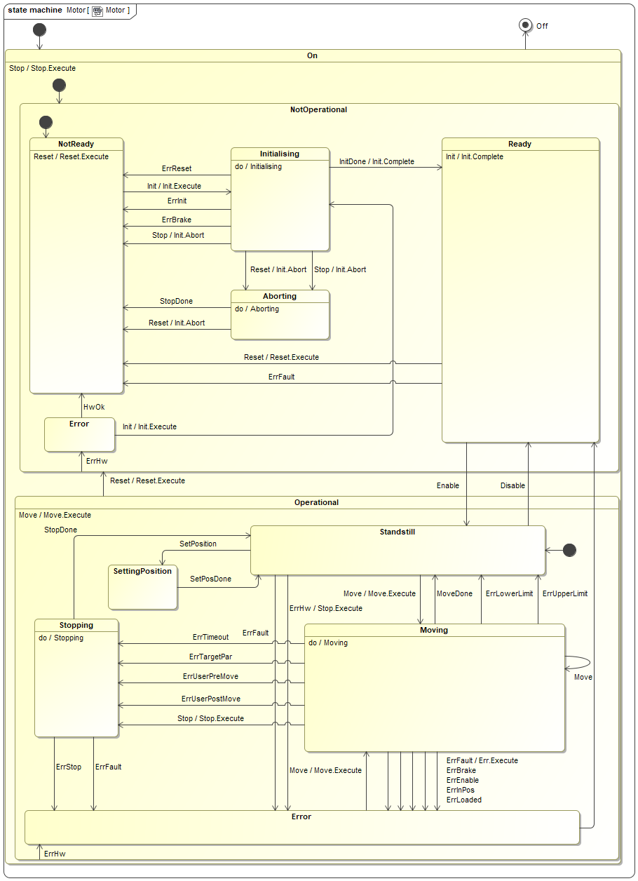
State Machine
The state machine of the motor controller is shown below. The main operational states are Standstill, Moving and Stopping.
Usage of NOVRAM
Note
Important note: If the motor is configured to use NOVRAM, the configuration of the motor is copied into NOVRAM on every successful INIT of the motor. If the INIT fails, the NOVRAM doesn’t get updated.
NOVRAM is used to store and keep the configuration of the motor. The configuration of the motor is copied into the NOVRAM on every successful INIT of the motor. On power cycle of the PLC, the configuration of the motor is read from the NOVRAM during the first PLC cycle. As a general rule, only PLCs with NOVRAM should be used for motor control applications, e.g. CX-2030 that comes with 128 kB of NOVRAM. PLCs without NOVRAM can still be used for motor control applications but the configuration will be lost on every power cycle of the PLC. These applications have to rely on the higher level software that has to download the configuration after each power cycle. The other option is to hard-code the configuration in the PLC application itself.
Input parameters

FB_MOTOR has three input parameters. Apart from the standard sName parameter for the name, i.e. the label, of the motor instance, there are two additional parameters related to the usage of the NOVRAM.
Parameter |
Type |
Description |
|---|---|---|
sName |
STRING |
Motor instance name/label |
nNOVRAM_DevId |
UDINT |
NOVRAM Device ID. For PLCs without NOVRAM, this parameter should be set to zero or not given at all. |
nNOVRAM_Offset |
UDINT |
Offset in bytes in NOVRAM. A motor instance needs about 500 bytes for configuration data. For simplicity it is recommended to increment offsets by 1000 for each motor. Therefore, the first motor will have the offset of zero, second of 1000, third of 2000, etc. For PLCs without NOVRAM, this parameter should be set to zero or not given at all. |
The following example shows the usage of NOVRAM. It is very important to note that the entered value for the parameter nNOVRAM_DevId matches the value of the NOV-DP-RAM device. In this example the value is 4.
In case that the NOVRAM is not used, the Motor1 instance would not have any NOVRAM related parameters and the code would look like this:
Motor1(sName:=’Motor1’);

Figure 7: Application example for using NOVRAM with FB_MOTOR.
Signal Mapping
Figure 8 shows the TwinCAT view of the FB_MOTOR I/O variables that are available for mapping to physical signals, i.e. ports of I/O terminals or NC structures.
The mapping is quite different from other devices. Specific to motors, for each Axis (i.e. motor) there are two links to be established from the Axes/<Motor> Settings:
Link To I/O… This is the link between the Axis and the motor controller terminal, e.g. EL7041, that controls it.
Link To PLC… This is the link between the Axis and the motor instance in the MAIN program, e.g. Motor1. This link sets all the mappings for the two complex structures NcToPlc (input) and PlcToNc (output) and the user should not touch it afterwards.
The mapping parameters are described in the table below.

Figure 8: Example of FB_MOTOR input/output signals.
Variable |
Port Type |
Optional |
Description |
|---|---|---|---|
switches |
Digital In |
Yes |
There are six variables to be linked to various limit and reference switches, depending on the HW configuration; upper and lower Stop and HW limits, Reference and Index switch. Switches can be linked to any binary signal (BOOL). Normally the signals are coming from digital inputs but they could also be linked to variables of type BOOL in some special applications, i.e. digitizing of analog position sensors. |
i_bInPos |
Digital In |
Yes |
Signal of the In-Position switch. In some applications with stepper motors without feedback (cryogenic environment) a switch is used to confirm that the motor is in correct position. |
i_bBrakeStat |
Digital In |
Yes |
Status of the brake feedback signal. |
i_nInfoData1/2 |
INT |
Yes |
Two freely selectable signed integers to be link to any variable of the same type, e.g. motor controller output current. |
i_nSoE_DriveStatus |
UINT |
Yes |
Serco Drive (e.g. AX5000) Status, not used with CoE drives. |
i_nSoE_PowerStatus |
UINT |
Yes |
Serco Drive (e.g. AX5000) Power Status, not used with CoE drives. |
i_nCouplerState |
UINT |
No |
Mapped to the ‘state’ of the coupler that hosts I/O terminals. If the terminals span over more than one coupler, it is recommended to select the ‘state’ of the last coupler that hosts a shutter signal. |
NcToPlc |
Struct In |
No |
Internal MC structure of type MC.NCTOPLC_AXIS_REF. Automatically linked from “Link To PLC”. |
q_bBrake_Ctrl |
Digital Out |
Yes |
Brake control digital output signal. Active low! |
PlcToNc |
Struct Out |
No |
Internal MC structure of type MC.PLCTONC_AXIS_REF. Automatically linked from “Link To PLC”. |
GUI Templates
The Motion Library provides two template GUIs intended for configuration and control of motor instances of FB_MOTOR respectively. Applications can easily deploy instances of the GUIs by setting the GUI references to the particular instance of FB_MOTOR_CONTROL, as shown below for the case of the configuration GUI.

Figure 9: Instantiation of GUI_TEMPLATE_MOTOR_CONFIG for Motor1
From the Configuration GUI, shown in Figure 10, it is very simple to set axis type, define INIT sequence, select user defined methods to be executed, set the active low parameters for each switch, as well as to configure brakes, define timeouts, software limits and backlash compensation.
Once the motor is successfully initialised, the complete configuration will be stored in NOVRAM.

Figure 10: FB_MOTOR HMI for motor configuration.
From the Control GUI, shown in Figure 11, it is possible to perform basic control operations on the motor.

Figure 11: FB_MOTOR HMI for Local Control.
Motor specific RPC Methods
RPC_MoveAbs() Move to absolute position
RPC_MoveRel() Move relative to current position
RPC_MoveVel() Move in velocity
Motor Simulator
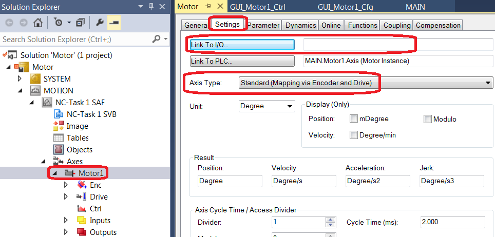
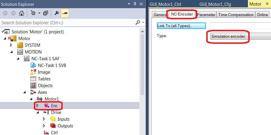
Note
Important note: In order to use the motor simulator, the Axis has to be modified. The Axis Type has to be set to Standard (Mapping via Encoder and Drive) and the Link to I/O… should be left empty. The Axis Encoder has to be configured as Simulation encoder. See screen shots below.
The function block FB_SIM_MOTOR implements the motor simulator on the PLC. The input parameter of the simulator are addresses of the motor instance configuration and status structures. The following code shows how the simulator is declared and executed:
Declaration:
{attribute 'OPC.UA.DA':='1'}

Motor1: FB_MOTOR;

{attribute 'OPC.UA.DA':='1'}

SIM_Motor1: FB_SIM_MOTOR;
Execution:
Motor1(sName:='Motor1', nNOVRAM_DevId:=0);

SIM_Motor1 (ptrCfg:=ADR(Motor1.cfg), ptrStat:=ADR(Motor1.stat));
Simulator Mapping

Simulator RPC Methods
User Defined Methods
The functionality of FB_MOTOR can be extended by user defined Pre- and Post INIT and MOVE methods. FB_MOTOR already includes the four dummy methods (see below) that only add a delay of three seconds during the execution. However, the dummy implementation can be a good starting point when overloading these methods for specific implementations in FBs that extend the FB_MOTOR functionality.

Module ASTRO (FB_ASTRO)
FB_ASTRO is the FB written in ST that provides the functionality similar to what is provided in the C++ modules TrkParams and TrkModule in the CCS Simulator (ccssim.library). The main purpose of this FB is to simulate the sky data in the format that is going to be provided by the CCS.
FB_ASTRO works in combination with FB_TIME (see timer.library) that provides real or simulated time.
Input parameters:
Variable |
Type |
Description |
|---|---|---|
in_TimeStat |
REFERENCE TO T_TIME_STAT |
REF to FB_TIME.stat structure |
in_Ra_hhmmss |
LREAL |
RA of sky object [hhmmss.sss] |
in_Dec_ddmmss |
LREAL |
Dec of sky object [ddmmss.sss] |
in_nTel |
E_ASTRO_TELESCOPE |
Telescope, ELT, UT1-4. Default ELT |
Depending on the value of the in_nTel parameter, proper values for the telescope longitude, latitude and hight will be internally set.
Output parameters:
Variable |
Type |
Description |
|---|---|---|
out_CcsDeterministic |
T_ASTRO_POINTING_KERNEL_POSITIONS |
Simulated CCS MUDPI data |
Signal Mapping
FB_ASTRO also provides an identical structure to T_ASTRO_POINTING_KERNEL_POSITIONS, to be used by applications that expect data through signal mapping. The output structure is called q_trk_data.
Methods
There are two methods of FB_ASTRO that provide the interface to programmatically modify the RA and Dec coordinates of the simulated sky object.
Method |
Description |
|---|---|
M_SetRaDec_hdmmss |
Set absolute (RA,Dec) coordinates [hh/dd mmss.sss] |
M_OffsetRaDec_arcsec |
Apply offsets to current (RA,Dec) coordinates [arcsec] |
The example below shows how to use the FBs in a PLC program, using the default parameters for RA, Dec and the telescope.
Declaration:
{attribute 'OPC.UA.DA':='1'}
time_data:      FB_TIME;

astro:          FB_ASTRO;
Execution:
//
// Time handling.
// It handles IEEE1588, NTP, Local and Simulated time.
//
time_data();

//
// Simulation of data coming from the TEL via MUDPI.
//
astro(in_TimeStat          := time_data.stat,
      out_CcsDeterministic => ccsDeterministic);
GUI Template
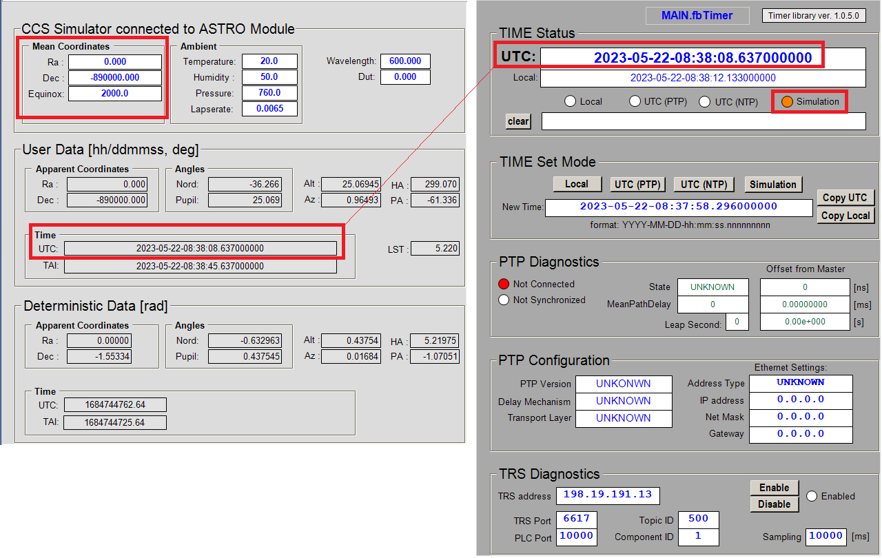
The GUI template GUI_TEMPLATE_ASTRO_CCS_SIM is almost identical to the GUI template GUI_TEMPLATE_CCS_SIM, but it is customized to work with FB_ASTRO instead of FB_CCS_SIM. An instance of the GUI based on GUI_TEMPLATE_ASTRO_CCS_SIM is shown below, together with the corresponding GUI for the simulated time.
Note that the initial RA and Dec sky object coordinates that are passed as input parameters to the instance of FB_ASTRO can be overwritten from the GUI.
Note
By using FB_ASTRO and FB_TIME, it is possible to develop and test instrument SW without the need for the connection to the CCS nor to the time network. Any sky object position, and any date and time, past or future, can be selected.
Utils Library (utils.library)
This is a small PLC library that provides some utility Function Blocks. Currently this library includes convenient FB for sending/receiving MUDPI packets and for listening and storing event logs.
CCS Simulator (ccssim.library)
Tracking devices require information from CCS to be able to compute the corrections to be applied to the actuators. This information will be delivered from CCS but in the meantime, FCF includes a utility that enable a simple way to validate tracking without the CCS infrastructure. It is a dummy FB (FB_CCS_SIM) that can be edited to define the telescope coordinates, environmental conditions and other parameters needed by a couple of C++ modules computing the tracking data.
The ccssim Library includes two C++ modules that work together to compute the tracking data:
TrkParams
TrkModule
The trkParams computes the parameters used by the slalib library and it does not require to be executed at a fast rate. The trkModule is the one computing the tracking data and it should be configured to run in a task running faster than the trkParams. It is suggested to use isolated CPU cores in order to maximize performance, as shown in the figure below where one CPU core is dedicated to the more demanding tasks.
Suggestion for PLC CPU assignments for C++ modules supporting the ccssim library.
Note
This library has been updated in FCF version 4 to send the tracking data via MUDPI protocol. This is achieved by having a dedicated task running at 20Hz and sending the CCS data using UDP (MUDPI).
The ccssim library requires the utils library which provides the methods to encode and decode MUDPI and the timer library to deliver the absolute time.
Note
An sample project implementing a CCS receiver can be found in the ifw-resources project.
Input parameters
The FB_CCS_SIM does not have input parameters.
Signal Mapping
Figure below shows an example of the mapping related to the CCS Simulator (ccs_sim). It relates to the C++ modules, an instance to the FB_TIME (time_info) and a tracking device such a the derotator (drot).

Example of the FB_CCS_SIM mapping.
The specific mapping parameters of CCS Simulator are described in the table below.
Variable |
Port Type |
Optional Mapping |
Description |
|---|---|---|---|
i_trk_data |
PointingKernel |
No |
Structure delivered by the C++ Module |
q_ccs_data |
CcsData |
No |
Structure containing the complete CCS data |
q_mudpi_cfg |
T_MUDPI_CFG |
No |
Structure containing MUDPI configuration |
q_mean_coordinates |
TrkMeanCoordinates |
No |
Structure containing the MEAN coordinates |
q_timeinfo |
TimeInfo |
No |
Structure containing the time information |
GUI Template
As for the other FBs, the ccsim Library provides a template GUI to control the FB_CCS_SIM. Applications can easily deploy an instance of this GUI to control their own time function block by setting the GUI references to the particular instance of the FB_CCS_SIM. However applications can use directly the project included in the ccssim library.
Instantiation of GUI_TEMPLATE_CCS_SIM for ccs_sim
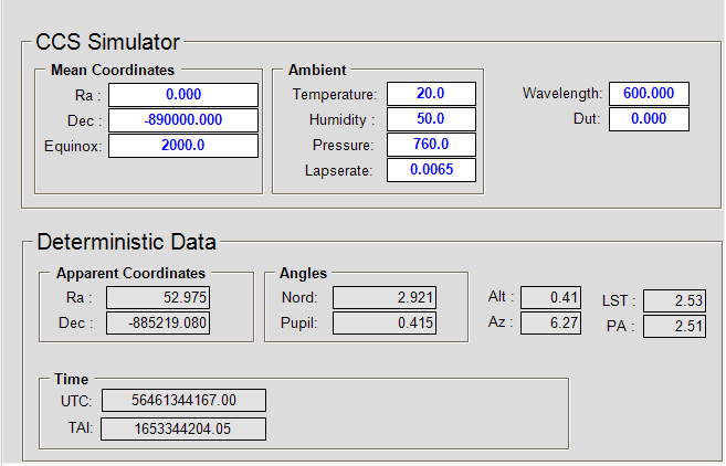
FB_CCS_SIM HMI for Local Control.
CCS_SIM specific RPC Methods
RPC_SetCoordinates() This RPC allows the user to change RA,DEC and EQUINOX via OPCUA.
CCS Library (ccslib.library)
This is a small PLC library that can be used to receive CCS data and interpolate it before it is passed to the tracking devices.
Warning
The ccslib library requires the TwinCAT TCP/IP (TF6311) to receive MUDPI data through the network. To learn how to configure the Beckhoff TF6311, please refer to the TwinCAT documentation.
Drot Controller (motor.library)
FB_MA_DROT is the TwinCAT PLC Function Block used to operate a derotator. The FB encapsulates the motion control functionality using a composition of a motor device together with the functionality to derive the next motor position using the field rotation obtained from CCS.
Note
All the functionalities provided for a normal motor device are available as well for the derotator.
Input parameters
FB_MA_DROT has four input parameters. Apart from the standard sName parameter for the name, i.e. the label, of the derotator instance, there are three additional parameters used by the motor used internally by the derotator.
Parameter |
Type |
Description |
|---|---|---|
sName |
STRING |
Drot instance name/label |
sMotorName |
STRING |
Motor instance name/label |
in_lrRotation |
LREAL |
Rotation used for Sky mode |
in_lrPupil |
LREAL |
Pupil rotation used for Elevation mode |
in_lrParallactic |
LREAL |
Parallactic angle |
nNOVRAM_DevId |
UDINT |
NOVRAM Device ID. For PLCs without NOVRAM, this parameter should be set to zero or not given at all. |
nNOVRAM_Offset |
UDINT |
Offset in bytes in NOVRAM. A motor instance needs about 500 bytes for configuration data. For simplicity it is recommended to increment offsets by 1000 for each motor. Therefore, the first motor will have the offset of zero, second of 1000, third of 2000, etc. For PLCs without NOVRAM, this parameter should be set to zero or not given at all. |
Note
The usage of NOVRAM follows the same guidelines as for a FB_MOTOR.
Warning
Derotator input parameter have been modified in IFW version 5 beta.
In case that the NOVRAM is not used, a derotator instance would look like this:
drot(sName:='DROT', sMotorName:= 'DrotMotor',
        in_lrRotation :=astro.UserPointingKernel.north_angle,
        in_lrPupil := astro.UserPointingKernel.pupil_angle,
    in_lrParallactic := astro.UserPointingKernel.parallactic_angle);
Signal Mapping
The mapping includes all the mapping of a motor plus the specific mapping of the derotator.
Specific to the internal derotator motor, there are two links to be established from the Axes/<Motor> Settings:
Link To I/O… This is the link between the Axis and the motor controller terminal, e.g. EL7041, that controls it.
Link To PLC… This is the link between the Axis and the motor instance in the MAIN program, e.g. drot1.motor. This link sets all the mappings for the two complex structures NcToPlc (input) and PlcToNc (output) and the user should not touch it afterwards.
The description of the standard motor mapping can be found here motor-signal-mapping
GUI Templates
The Motion Library provides one template GUI intended for the control of instances of FB_MA_DROT. Applications can easily deploy instances of the GUI by setting the GUI reference to the particular instance of FB_MA_DROT.
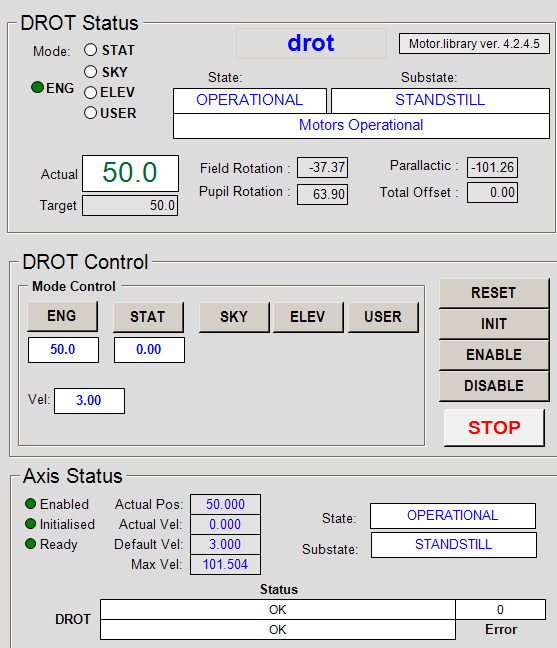
FB_MA_DROT HMI for Local Control
From the Derotator Control GUI, shown above, it is possible to perform basic control operations on the Derotator. The GUI also shows the status of the subordinated motor.
Note
It is possible to create dedicated control and configuration GUIs for the derotator subordinated motor as for any other motor device.
Derotator specific RPC Methods
RPC name |
Parameters |
Description |
|---|---|---|
RPC_MoveAngle() |
in_lrAngle |
Move the derotator to a particular position angle. |
RPC_StartTrack() |
in_mode in_angle |
Start derotator tracking. |
RPC_TrackOffset() |
in_lrOffset |
Performs a relative offset to the position during tracking. |
RPC_StopTrack() |
Stop derotator tracking. |
Derotator Simulator
Derotator does not have a dedicated simulator. Motor simulator shall be used to simulate derotator behaviour.
Declaration:
{attribute 'OPC.UA.DA':='1'}

drot:       FB_MA_DROT;

{attribute 'OPC.UA.DA':='1'}

sim_drot:   FB_SIM_MOTOR;
Execution:
drot(sName:='DROT', sMotorName:= 'DrotMotor',
        in_lrRotation :=astro.UserPointingKernel.north_angle,
        in_lrPupil := astro.UserPointingKernel.pupil_angle,
    in_lrParallactic := astro.UserPointingKernel.parallactic_angle);
sim_drot(ptrCfg:=ADR(drot.motor.cfg), ptrStat:=ADR(drot.motor.stat));
User Defined Methods
Derotator user defined functions are the same as for the Motor.
ADC Controller (motor.library)
FB_MA_ADC is the TwinCAT PLC Function Block used to operate a ADC. The FB encapsulates the motion control functionality using a composition of two internal motors (motor1 and motor2).
Note
All the functionalities provided for a normal motor device are available as well for the internal ADC motors.
Input parameters
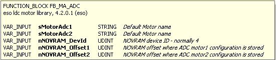
FB_MA_ADC has five input parameters as shown in figure above.
Note
The usage of NOVRAM follows the same guidelines as for FB_MOTOR.
Signal Mapping
The mapping includes all the mapping of the two internal motors plus the specific mapping of the ADC.
Specific to the internal ADC motors, there are two links to be established from each of the Axes/<Motor> Settings:
Link To I/O… This is the link between the Axis and the motor controller terminal, e.g. EL7041, that controls it.
Link To PLC… This is the link between the Axis and the motor instance in the MAIN program, e.g. drot1.motor. This link sets all the mappings for the two complex structures NcToPlc (input) and PlcToNc (output) and the user should not touch it afterwards.
The description of each standard motor mapping can be found here motor-signal-mapping
The additional ADC mapping parameters are described in the table below.
Variable |
Port Type |
Optional |
Description |
|---|---|---|---|
i_trk_data |
Struct In |
No |
Tracking data got from CCS. |
i_ccs_data |
Struct In |
Yes |
CCS Simulation data |
Warning
The above mapping table does not include the mapping for the two internal motors.
GUI Templates
The Motion Library provides one template GUI intended for the control of instances of FB_MA_ADC. Applications can easily deploy instances of the GUI by setting the GUI reference to the particular instance of FB_MA_ADC.
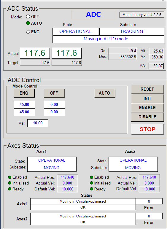
FB_MA_ADC HMI for Local Control
From the ADC Control GUI, shown on above, it is possible to perform basic control operations on the ADC. The GUI also shows the status of the subordinated motors.
Note
It is possible to create dedicated control and configuration GUIs for the ADC subordinated motors as for any other motor device.
ADC specific RPC Methods
RPC name |
Parameters |
Description |
|---|---|---|
RPC_MoveAngle() |
in_lrAngle |
Move the ADC to a particular position angle. |
RPC_StartTrack() |
in_angle |
Start ADC tracking. |
RPC_StopTrack() |
Stop ADC tracking. |
ADC Simulator
ADC does not have a dedicated simulator. Motor simulator shall be used to simulate the behaviour of the two internal motors.
Declaration:
{attribute 'OPC.UA.DA':='1'}
adc:       FB_MA_ADC;

{attribute 'OPC.UA.DA':='1'}
sim_adc1:   FB_SIM_MOTOR;

{attribute 'OPC.UA.DA':='1'}
sim_adc2:   FB_SIM_MOTOR;
Execution:
adc(sName           := 'ADC',
    sMotorAdc1      := 'AdcMotor1',
    sMotorAdc2      := 'AdcMotor2',
    nNOVRAM_DevId   := 4,
    nNOVRAM_Offset1 := 3000,
    nNOVRAM_Offset2 := 4000);

sim_adc1(ptrCfg:=ADR(adc.motor1.cfg), ptrStat:=ADR(adc.motor1.stat));
sim_adc2(ptrCfg:=ADR(adc.motor2.cfg), ptrStat:=ADR(adc.motor2.stat));
User Defined Methods
No user defined functions are provided by the ADC.
I/O Device Library (ioDev.library)
Note
The most common data type for analog signals is INT (16-bit signed). However, some I/O terminals, e.g. EL3692, can provide readings in user units of type REAL (FLOAT). ioDev.library supports both types of analog inputs.
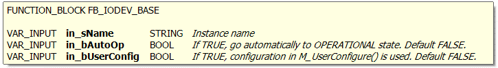
ioDev.library contains a number of FBs for handling analog (INT and REAL) and digital sensors and I/O devices. In addition, it provides FB methods for scaling of signals in order to work directly in user units (temperatures, pressures, etc), instead of displaying pure voltages that cannot be easily interpreted by the user before they are scaled at the WS level. Simulators for analog and digital signals are also provided. They might be of great help at the early stages of projects when sensors are not available yet or for testing of out‑of‑range conditions.
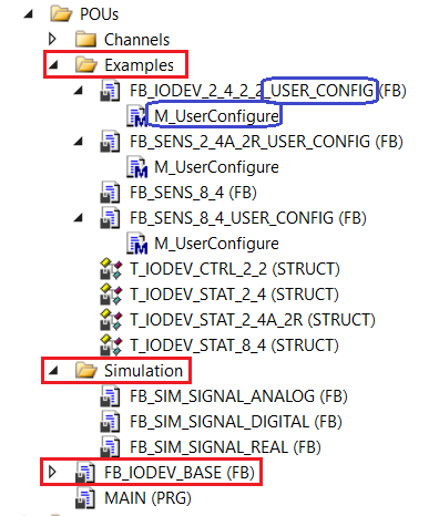
The library provides a Function Block called FB_IODEV_BASE that has to be extended and customised by the user by adding input and output signals to the status and control structures. A number of I/O and Sensor FB examples that extend the FB_IODEV_BASE functionality can be found in the Examples directory. Example FBs with the string ‘_USER_CONFIG’ in their name provide examples of user defined configuration, i.e. signal scaling, that is implemented in the M_UserConfigure() method. In addition to the extension of the FB functionality, the user has to extend the definition of the status T_IODEV_STAT and the control T_IODEV_CTRL structure (if any) by adding arrays of specific input and output signals.
Overview of ioDev.library
State Machine of Sensor
Sensor is a special case of the I/O Device that doesn’t have any outputs. The state machine of the sensor controller is shown below. The main operational state is Monitoring.
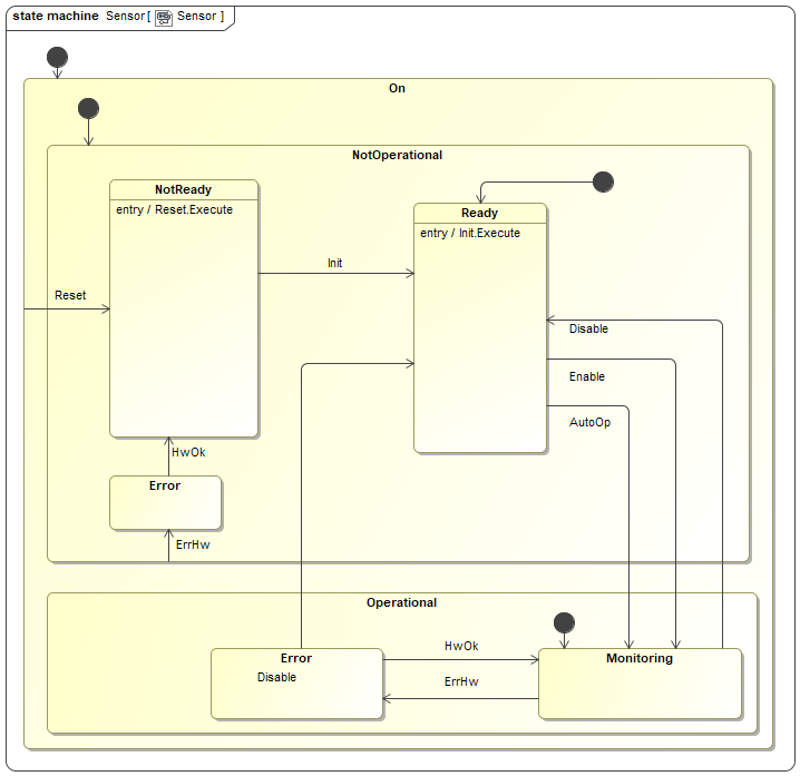
Note
All I/O devices start monitoring in the NotOp/Ready state.
Input parameters
User Customisation
As previously stated, the Function Block FB_IODEV_BASE provides all methods to handle I/O signals but no signals are defined. The FB has to be extended by the user by adding required I/O signals. The customisation process will be described through examples.
Example 1: I/O Device with User Defined Scaling
The FB FB_IODEV_2_4_2_2_USER_CONFIG is an example of the I/O device that handles 2 DI, 4 AI, 2 DO and 2 AO, with the user defined scaling.
The following steps have to be done:
Extend the T_IODEV_STAT structure by adding arrays of input signals. The new structure is called T_IODEV_STAT_2_4, meaning 2 digital inputs and 4 analog inputs.

Extend the T_IODEV_CTRL structure by adding arrays of output signals. The new structure is called T_IODEV_CTRL_2_2, meaning 2 digital outputs and 2 analog outputs.

Define signal scaling for both inputs and outputs in the M_UserConfigure() method.

Extend the functionality of FB_IODEV_BASE in newly created FB FB_IODEV_2_4_2_2_USER_CONFIG.
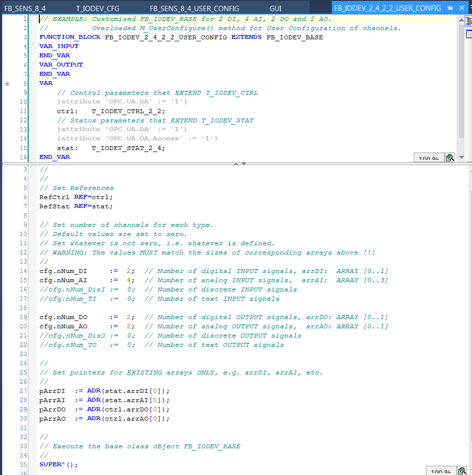
The code below shows all that the user has to do in order to define an FB that extends the functionality of FB_IODEV_BASE. The following has to be done in the FB:
In the declaration of FB FB_IODEV_2_4_2_2_USER_CONFIG, add ctrl and stat structures. They should be of type T_IODEV_CTRL_2_2 and T_IODEV_STAT_2_4, respectively.
Set references to ctrl and stat structures.
Set the number of existing I/O signals.
Set the pointers to the first item of each signal array.
Execute the code of the base (SUPER) FB.
Example 2: Sensor Device without User Defined Scaling
The Function Block FB_SENS_8_4 is an example of a sensor device for 8 digital and 4 analog input signals. The corresponding status data structure is called T_IODEV_STAT_8_4. Since there are no output signals, the standard control structure T_IODEV_CTRL is used. In this example user scaling is not used, so the scaling is supposed to be done on the WS.
The following steps have to be done:
Extend the T_IODEV_STAT structure by adding arrays of input signals. The new structure is called T_IODEV_STAT_8_4, meaning 8 digital inputs and 4 analog inputs.

Create a Function Block called FB_SENS_8_4 and extend the functionality of FB_IODEV_BASE, as shown below.
The code below shows all that the user has to do in order to define an FB that extends the functionality of FB_IODEV_BASE. The following has to be done in the FB:
In the declaration of FB_SENS_8_4, add ctrl and stat structures. Since this is a pure sensor, the standard ctrl structure of type T_IODEV_CTRL is used. The stat structure is declared as T_IODEV_STAT_8_4.
Set references to ctrl and stat structures.
Set the number of existing input signals.
Set the pointers to the first item of each signal array.
Execute the code of the base (SUPER) FB.

Signal Mapping
As an example, the figure below shows the TwinCAT view of the FB_IODEV_2_4_2_2_USER_CONFIG I/O variables that are available for mapping to physical signals, i.e. ports of analog and digital I/O terminals.

Figure 12: Example of a FB_IODEV_2_4_2_2_USER_CONFIG signals.
The table below describes each mapping variable.
Variable |
Port Type |
Optional |
Description |
|---|---|---|---|
i_nCouplerState |
UINT |
No |
Mapped to the ‘state’ of the coupler that hosts I/O terminals. If the terminals span over more than one coupler, it is recommended to select the ‘state’ of the last coupler that hosts a shutter signal. |
arrDI[i].i_bValue |
BOOL |
Yes |
Array of digital input signals |
arrAI[i].i_nValue |
INT |
Yes |
Array of analog input signals |
arrDO[i].q_bValue |
BOOL |
Yes |
Array of digital output signals |
arrAO[i].q_nValue |
INT |
Yes |
Array of analog output signals |
GUI Template
The IODev Library provides a template GUI GUI_TEMPLATE_IODEV for the FB_IODEV_BASE FB. The GUI can be also used for the Function Blocks that extend the FB_IODEV_BASE functionality. Applications can easily deploy an instance of this GUI by setting the GUI references to the particular instance of the FB, as shown below.
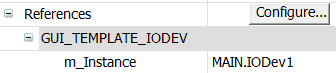
Instantiation of GUI_TEMPLATE_IODEV for IODev1
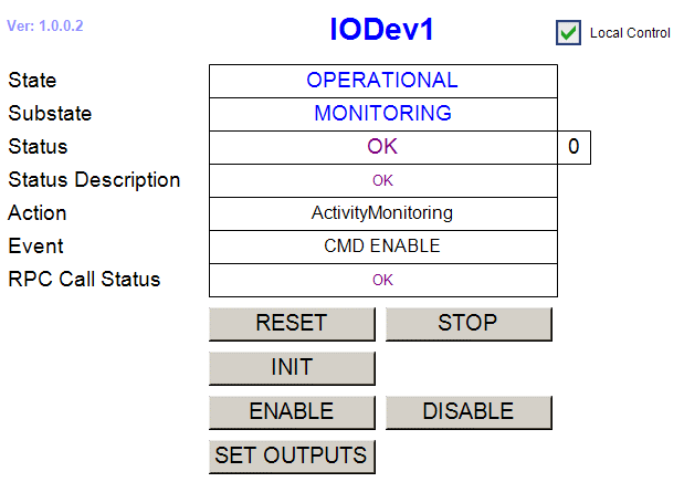
FB_IODEV_BASE HMI for Local Control.
IODev specific RPC Methods
RPC_SetOutputs() Activate IODev outputs (not used with pure sensors)
Signal Simulators
The ioDev.library provides individual analog and digital signal simulators. This means that if the user wants to simulate all signals of a sensor with eight digital and four analog signals, for example, he will have to instantiate eight digital and four analog signal simulators. However, for testing purposes it might be needed to simulate just a few signals. Time parameters are given in milliseconds.
The function blocks FB_SIM_SIGNAL_ANALOG and FB_SIM_SIGNAL_REAL implement simulated analog sinusoidal signals of type INT and REAL, respectively. The input parameters are the same for both FBs:

The function block FB_SIM_SIGNAL_DIGITAL implements a simulated digital signal. The input parameters are:

The following source code example is the Program MAIN that is delivered with the library. The code shows how to configure sensors as well as simulators whose outputs could be mapped to sensor input variables.
Declaration:
// IMPORTANT: In order to access RPC Calls via OPC UA,
//            attribute 'OPC.UA.DA':='1' is needed!!!
{attribute 'OPC.UA.DA':='1'}
IODev1:     FB_IODEV_2_4_2_2_USER_CONFIG;
{attribute 'OPC.UA.DA':='1'}
IODev2:     FB_SENS_8_4;
{attribute 'OPC.UA.DA':='1'}
IODev3:     FB_SENS_8_4_USER_CONFIG;
{attribute 'OPC.UA.DA':='1'}
IODev4:     FB_SENS_2_4A_2R_USER_CONFIG;

// Simulated signals
//
// Digital
SIM_bDig1:  FB_SIM_SIGNAL_DIGITAL;
SIM_bDig2:  FB_SIM_SIGNAL_DIGITAL;

// Analog
SIM_nAnlg1: FB_SIM_SIGNAL_ANALOG;
SIM_nAnlg2: FB_SIM_SIGNAL_ANALOG;
SIM_nAnlg3: FB_SIM_SIGNAL_ANALOG;
SIM_nAnlg4: FB_SIM_SIGNAL_ANALOG;

SIM_rAnlg1: FB_SIM_SIGNAL_REAL;
SIM_rAnlg2: FB_SIM_SIGNAL_REAL;
Execution:
//
// Simulated signals
//
SIM_bDig1(in_nPeriodLow:=5000, in_nPeriodHigh:=2000);
SIM_bDig2(in_nPeriodLow:=2000, in_nPeriodHigh:=4000);

SIM_nAnlg1(in_nPeriod:=10000, in_nScale:=10000.0, in_nOffset:=0);
SIM_nAnlg2(in_nPeriod:=10000, in_nScale:=100.0,   in_nOffset:=5000);
SIM_nAnlg3(in_nPeriod:=10000, in_nScale:=10.0,    in_nOffset:=1000);

// Simulation of Edwards pressure guage
// Vary input from 4.5 to 5.0 V
// 16-bit A/D converter, +=10V, e.g. EL3102.
// 1V = 2^16/10/2 = 3276.8 bit
// 4.5 to 5.0 V ==> 4.5*3276.8 to 5.0*3276.8 bit ==> 14745 to 16384
// in_nScale = (16384 - 14745) / 2 = 819.5
// in_nOffset = 14745 + 819.5 = 15564.5
SIM_nAnlg4(in_nPeriod:=30000, in_nScale:=819.5, in_nOffset:=15564);


SIM_rAnlg1(in_nPeriod:=20000, in_nScale:=1000.0, in_nOffset:=1000.0);
SIM_rAnlg2(in_nPeriod:=10000, in_nScale:=100.0,  in_nOffset:=0.0);


//
// Real devices
//

//
// IODev1
//
// The device will go directly to OP/MONITORING on PLC reboot.
// The configuration defined in M_UserConfigure() will be applied.
IODev1(in_sName:='IODev1', in_bAutoOp:= TRUE, in_bUserConfig:=TRUE);

//
// IODev2
//
// The device will go directly to OP/MONITORING on PLC reboot.
// The configuration defined in M_UserConfigure() will NOT be applied.
IODev2(in_sName:='IODev2', in_bAutoOp:= TRUE);

//
// IODev3
//
// The device will go directly to OP/MONITORING on PLC reboot.
// The configuration defined in M_UserConfigure() will be applied.
IODev3(in_sName:='IODev3', in_bAutoOp:= TRUE, in_bUserConfig:=TRUE);

//
// IODev4
//
// The device will go directly to OP/MONITORING on PLC reboot.
// The configuration defined in M_UserConfigure() will be applied.
IODev4(in_sName:='IODev4', in_bAutoOp:= TRUE, in_bUserConfig:=TRUE);
Simulator Mapping

Communication Libraries (rsComm*.library)
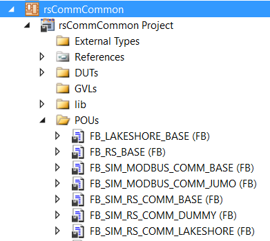
Module rsComm contains PLC libraries for communication via serial port, Ethernet Tcp and Ethernet Tcp RT (Ethernet Tcp Real-Time). The libraries are delivered under separate PLC projects as part of the rsComm TwinCAT solution. The reason for this is that each communication protocol requires a separate license, so the functionality is provided per license. The four PLC projects are shown in the figure below.
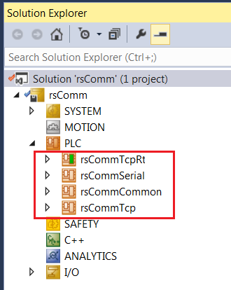
The overview of all Function Blocks is shown in the figure below. The FBs are color-coded in order to indicate the corresponding PLC project they belong to.
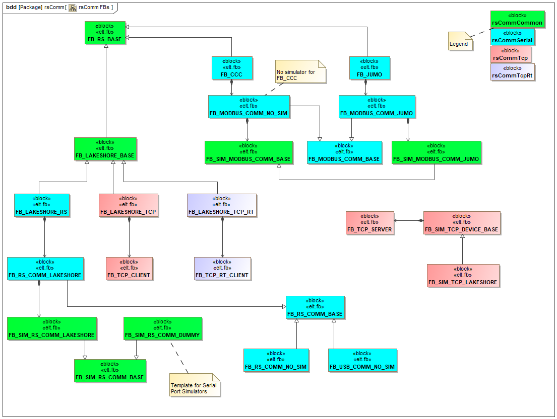
The following table gives the overview of the libraries.
Library |
Description |
|---|---|
rsCommCommon |
Common library that has to be included in every project using rsComm* libraries |
rsCommSerial |
Serial port communication and modbus RTU |
rsCommTcp |
TCP/IP communication via EtherCAT switch ports EL6601 and EL6614 |
rsCommTcpRt |
TCP/IP Real-Time communication via CX2500-0060 |
rsCommCommon.library
This is the common library that has to be included under References in all projects that use other rsComm* libraries. This library does not require any license. The Function Block FB_RS_BASE provides the common state machine for all controllers. All rsComm PLC controllers, Serial, Tcp and TcpRt, extend the functionality of this FB.
The overview of FBs is given in the following table.
Function Block |
Description |
|---|---|
FB_RS_BASE |
Base FB for all rsComm controllers. |
FB_LAKESHORE_BASE |
Base FB for all Lakeshore controllers, regardless of the comm interface. |
FB_SIM_MODBUS_COMM_BASE |
Base FB for MODBUS simulation. |
FB_SIM_MODBUS_COMM_JUMO |
JUMO MODBUS simulator. |
FB_SIM_RS_COMM_BASE |
Base FB for RS-232/422/485 simulation. |
FB_SIM_RS_COMM_DUMMY |
Example of RS comm simulator implementation. |
FB_SIM_RS_COMM_LAKESHORE |
RS based comm simulator for Lakeshores with serial port, i.e. models 218 & 340. |
There are two base FBs for RS comm simulation, FB_SIM_MODBUS_COMM_BASE and FB_SIM_RS_COMM_BASE. Their main purpose is to provide methods that generate simulated replies that include the reply terminators as well. The replies could have fixed values as well as simulated variations. The methods are shown on the following figure.
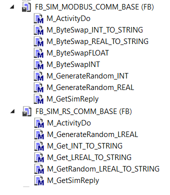
There are two methods, M_GetSimReply() and M_ActivityDo(), that should be customised for a particular simulator, e.g. for a Lakeshore 340 simulator. M_GetSimReply() should construct a reply based on the command. M_ActivityDo() might be used to provide more realistic behaviour, e.g. to simulate a Lakeshore warm-up ramp. For more info, please see method M_GetSimReply() of FB_SIM_RS_COMM_LAKESHORE.
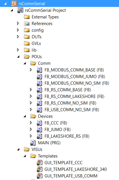
rsCommSerial.library
This library handles communication via serial line, e.g. via the EL6001 or the EL6021. In addition to the FBs handling ASCII serial (RS-232/422/485) and modbus RTU communication protocols, it provides controllers for the standard equipment used at ESO that have the serial port interface, like the Lakeshore 340 temperature controller or the ESO Cabinet Cooling Controller. It requires the TF6340 Serial Communication license. The MODBUS protocol is implemented in FB_MODBUS_COMM_BASE. Therefore, the TF6255 Modbus RTU license is not needed!
The overview of FBs is given in the table below.
Function Block |
Description |
|---|---|
FB_MODBUS_COMM_BASE |
Base FB for generic modbus RTU communication driver via serial port. |
FB_MODBUS_COMM_JUMO |
Modbus RTU communication driver customised for JUMO simulation. |
FB_MODBUS_COMM_NO_SIM |
Modbus RTU communication driver without any simulator |
FB_RS_COMM_BASE |
Base FB for generic RS-232/422/485 communication driver. |
FB_RS_COMM_LAKESHORE |
RS-232/422/485 communication driver customised for Lakeshore simulation. |
FB_RS_COMM_NO_SIM |
Generic RS-232/422/485 communication driver without a simulator. |
FB_USB_COMM_NO_SIM |
Generic USB communication driver without a simulator. |
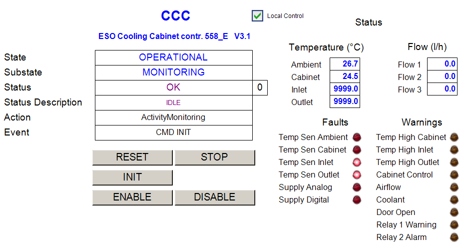
FB_CCC |
Driver for ESO standard Cabinet Cooling Controller with RS-232 interface. |
FB_JUMO |
JUMO driver with modbus RTU interface. |
FB_LAKESHORE_RS |
Lakeshore driver for devices with serial port, i.e. models 218 & 340. |
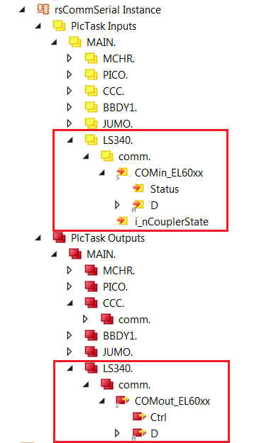
Signal Mapping
Apart from the common i_nCouplerState input parameter that has to be mapped to any of the State variables on the PLC, the mapping has to be done for input and output parameters of the serial port.
The serial port communication parameters, like baud rate, etc, have to be configured via the CoE interface.
The default CoE configuration for the Lakeshore 340 is given below.

GUI Templates
GUI templates for the ESO Cabinet Cooling Controller and the Lakeshore 340 temperature controller are provided.

Example code
The following code handles an ESO Cabinet Cooling Controller, a JUMO controller and a Lakeshore 340.
PROGRAM MAIN
VAR
        // ESO Cabinet Cooling Controller (RS-232 interface)
        {attribute 'OPC.UA.DA' := '1'}
        CCC:        FB_CCC;

        // JUMO Controller (modnus RTU via Serial)
        {attribute 'OPC.UA.DA' := '1'}
        JUMO:       FB_JUMO;

        // Lakeshore 340 (RS-232 interface)
        {attribute 'OPC.UA.DA' := '1'}
        LS340:      FB_LAKESHORE_RS;

END_VAR
CCC(in_sName:='CCC', in_nPeriod := 1200);

JUMO(in_sName:='JUMO',in_nPeriod:=1000);    // Read all JUMOs every second


LS340(
    in_bSimulation      := FALSE,
    in_sName            := 'Lake 340',
    in_nModel           := 340,
    in_bAutoMonitor     := TRUE,
    in_sCmdSuffix         := '$0D$0A',
    in_sReplySuffix       := '$0D$0A',
    in_nPeriod          := 1700);
rsCommTcp.library
Note
Usage of the rsCommTcp.library in combination with the EtherCAT switch ports EL6601 and EL6614 is the preferred option over the usage of the CX2500-0060 Realtime network adapter (see rsCommTcpRt.library).
This library handles the TCP/IP communication via EtherCAT switch ports EL6601 and EL6614. It can be used to communicate with devices equipment with the Ethernet port, e.g. the Lakeshore 336 temperature controller. It requires the TF6310 TCP/IP license. In addition, the TF6310 function Windows driver has to be installed on the PLC. The IP address of the switch has to match the subnet of the device connected to it. For more info about installation and licensing consult Beckhoff documentation.
The library provides generic TCP/IP drivers for TCP clients (FB_TCP_CLIENT) and servers (FB_TCP_SERVER). Device PLC controllers are based on FB_TCP_CLIENT, while FB_TCP_SERVER is used only for simulators.
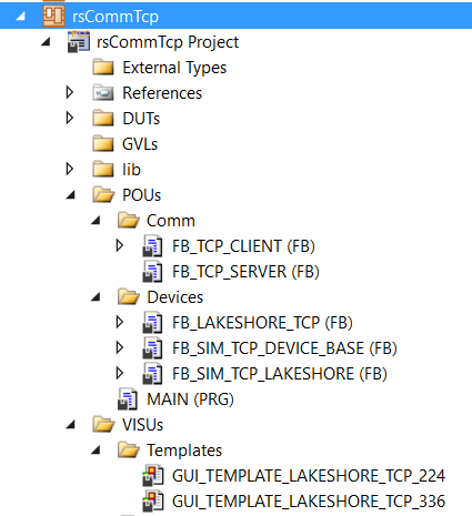
The overview of FBs is given in the table below.
Function Block |
Description |
|---|---|
FB_TCP_CLIENT |
Generic TCP/IP Client driver. This is the base FB for Tcp based controllers. |
FB_TCP_SERVER |
Generic TCP/IP Server driver. This is the base FB for the communication part of Tcp based simulators. |
FB_LAKESHORE_TCP |
Lakeshore driver for devices with Ethernet port, i.e. models 224 & 336. |
FB_SIM_TCP_DEVICE_BASE |
Generic TCP/IP device simulator that uses FB_TCP_SERVER for communication. |
FB_SIM_TCP_LAKESHORE |
TCP/IP device simulator for Lakeshore models 224 & 336. |
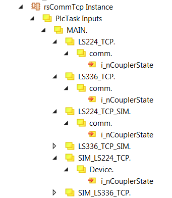
Signal Mapping
Devices and simulators have only a single input parameter (i_nCouplerState) to be mapped to any of the State variables on the PLC.
GUI Templates
GUI templates for the Lakeshore 336 and 224 temperature controller/monitor are provided.


Example code
The following code handles two real Lakeshore devices (224 and 336) and two additional Lakeshore devices that are connected to simulators. It is important to note that the devices that use simulators have to use the IP address ‘127.0.0.1’. Also, the port numbers of the device and the simulator have to match.
PROGRAM MAIN
VAR
    // Lakeshore 224 (Ethernet interface)
    {attribute 'OPC.UA.DA' := '1'}
    LS224_TCP:     FB_LAKESHORE_TCP;                // LakeShore based on FB_TCP_CLIENT

    // Lakeshore 336 (Ethernet interface)
    {attribute 'OPC.UA.DA' := '1'}
    LS336_TCP:     FB_LAKESHORE_TCP;                // LakeShore based on FB_TCP_CLIENT


    // Lakeshores to be simulated
    {attribute 'OPC.UA.DA' := '1'}
    LS224_TCP_SIM: FB_LAKESHORE_TCP;                // LakeShore based on FB_TCP_CLIENT
    {attribute 'OPC.UA.DA' := '1'}
    LS336_TCP_SIM: FB_LAKESHORE_TCP;                // LakeShore based on FB_TCP_CLIENT

    // Simulators
    SIM_LS224_TCP: FB_SIM_TCP_LAKESHORE;            // LakeShore SIM based on FB_TCP_SERVER
    SIM_LS336_TCP: FB_SIM_TCP_LAKESHORE;            // LakeShore SIM based on FB_TCP_SERVER


END_VAR
// Lakeshore 224
LS224_TCP(
    in_sName            := 'LS224_TCP',
    in_nModel           := 224,
    in_nPeriod          := 1500,
    in_sCmdSuffix         := '$0D$0A',
    in_sReplySuffix       := '$0D$0A',
    in_sDeviceTcpIpAdr  := '192.168.0.12',
    in_nDeviceTcpPort   := 7777);

// Lakeshore 336
LS336_TCP(
    in_sName            := 'LS336_TCP',
    in_nModel           := 336,
    in_nPeriod          := 1000,
    in_sCmdSuffix         := '$0A',
    in_sReplySuffix       := '$0A',
    in_sDeviceTcpIpAdr  := '192.168.0.80',
    in_nDeviceTcpPort   := 7777);

// Dummy Lakeshore 224
// in_bSimulation:= TRUE means that it communicates with a simulator.
// If the simulator is running on the same PLC, in_sDeviceTcpIpAdr:='127.0.0.1'.
// in_nDeviceTcpPort has to match simulator's in_nTcpPort.
// See SIM_LS224_TCP.
LS224_TCP_SIM(
    in_bSimulation      := TRUE,
    in_sName            := 'LS224_TCP_SIM',
    in_nModel           := 224,
    in_nPeriod          := 1500,
    in_sCmdSuffix         := '$0D$0A',
    in_sReplySuffix       := '$0D$0A',
    in_sDeviceTcpIpAdr  := '127.0.0.1',
    in_nDeviceTcpPort   := 8888);

// Dummy Lakeshore 336
// in_bSimulation:= TRUE means that it communicates with a simulator.
// If the simulator is running on the same PLC, in_sDeviceTcpIpAdr:='127.0.0.1'.
// in_nDeviceTcpPort has to match simulator's in_nTcpPort.
// See SIM_LS336_TCP.
LS336_TCP_SIM(
    in_bSimulation      := TRUE,
    in_sName            := 'LS336_TCP_SIM',
    in_nModel           := 336,
    in_nPeriod          := 1000,
    in_sCmdSuffix         := '$0A',
    in_sReplySuffix       := '$0A',
    in_sDeviceTcpIpAdr  := '127.0.0.1',
    in_nDeviceTcpPort   := 7777);


// Lakeshore simulators
SIM_LS224_TCP(
    in_bSimulation      := TRUE,
    in_bEnable          := TRUE,
    in_nModel           := 224,
    in_sReplySuffix       := '$0D$0A',
    in_sTcpIpAdr        := '127.0.0.1',
    in_nTcpPort         := 8888);

SIM_LS336_TCP(
    in_bSimulation      := TRUE,
    in_bEnable          := TRUE,
    in_nModel           := 336,
    in_sReplySuffix       := '$0A',
    in_sTcpIpAdr        := '127.0.0.1',
    in_nTcpPort         := 7777);
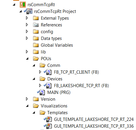
rsCommTcpRt.library
This library handles the TCP/UDP communication via CX2500-0060 system module that provides two independent Gbit Ethernet interfaces to the CX2000 family of PLCs, e.g. to the CX2030. The library can be used to communicate with devices equipment with the Ethernet port, e.g. the Lakeshore 336 temperature controller. It requires the TF6311 TC3 TCP/UDP Realtime license. The IP address of the switch has to match the subnet of the device connected to it. For more info about installation and licensing, consult Beckhoff documentation.

Warning
If the CX2500-0060 system module is installed, the PCI Bus address of the EtherCAT Device will be changed from the default 4/0 (0xF0020000) to 8/0 (0xF0020000), and an attempt to download an existing project will result in a failure message that is impossible to understand. For new projects the system will recognise the address automatically, while for the existing ones the new address has to be set by pressing the ‘Search…’ button and selecting the only available PCI Bus address, as seen on the figure below.

The library provides a generic TCP/UDP RT driver for TCP RT clients (FB_TCP_RT_CLIENT) that is used in PLC controllers for the equipment with the Ethernet interface, e.g. the Lakeshore 336.
The overview of FBs is given in the table below.
Function Block |
Description |
|---|---|
FB_TCP_RT_CLIENT |
Generic TCP/UDP RT Client driver. |
FB_LAKESHORE_TCP_RT |
Lakeshore driver for devices with Ethernet port, i.e. models 224 & 336. |
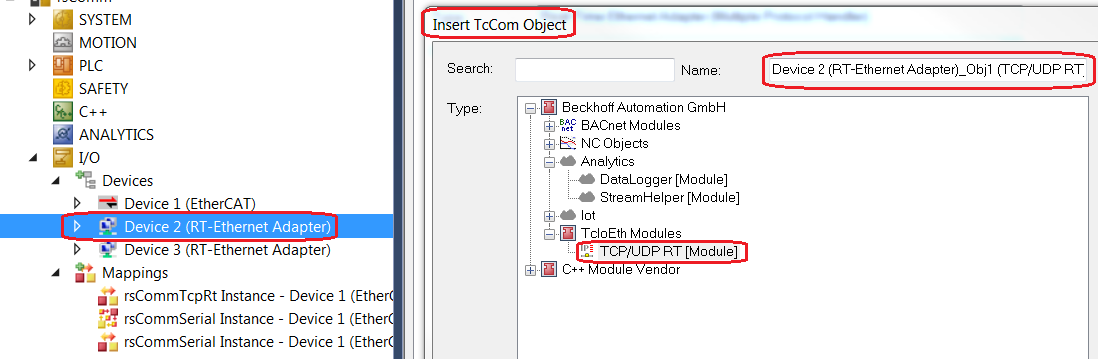
Adapter Configuration
The CX2500-0060 system module is not part of the EtherCAT network and there is no ‘clasical’ EtherCAT I/O mapping. Each network port has to be added manually under the I/O Devices as an RT-Ethernet Adapter. Then, an Object of type TCP/UDP RT, that can be found under Beckhoff/TcIoEth Modules, has to be added to the adaptor, e.g. Device 2 (RT-Ethernet Adapter)_Obj1 (TCP/UDP RT).
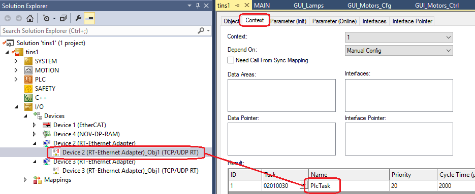
The Context of the Object is the PLC Task where an instance of the devices, e.g. MAIN.LS224_TCP_RT, will be running.
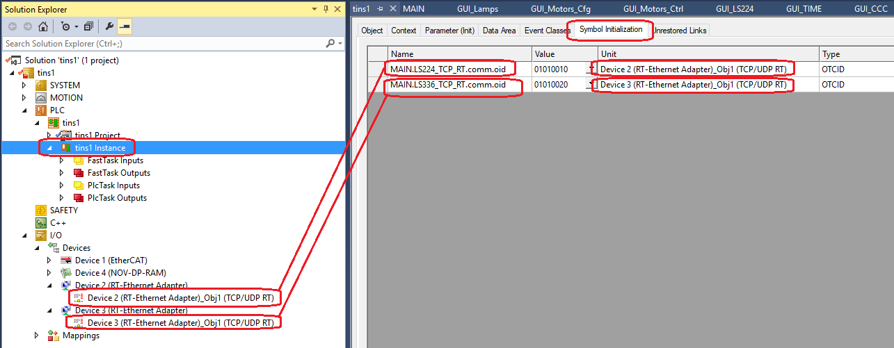
In the ‘Symbol Initialisation’ the Object has to be linked to the device instance.
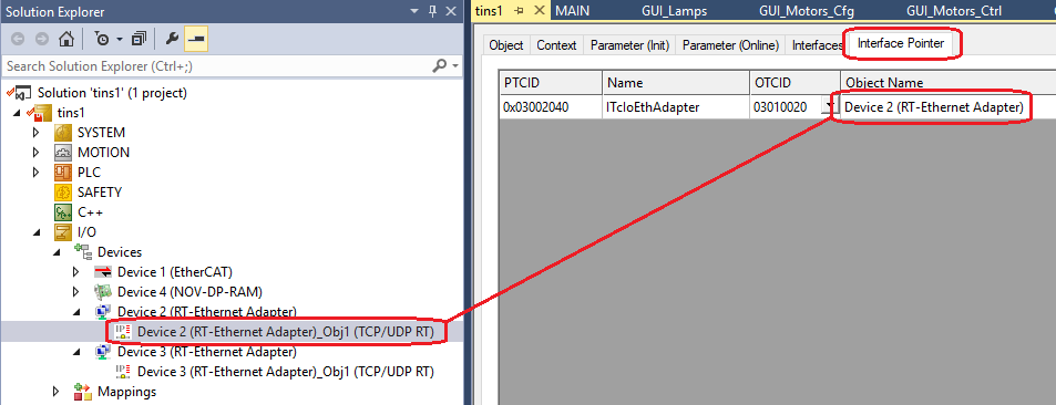
The ‘Interface Pointer’ has to be set to the Device Object.
In the case of a Lakeshore device connected to the RT-EthernetAdapter Object, the TcpTimeoutIdle, that can be found under ‘Parameter (Init)’, has to be set to 30 ms. This is a Lakeshore specific setting.

GUI Templates
GUI templates for the Lakeshore 336 and 224 temperature controller/monitor are provided. See the corresponding section for Lakeshore TCP devices. The GUIs look the same.
Example code
The following code handles two Lakeshore devices (224 and 336).
PROGRAM MAIN
VAR
        //
        // Tcp RT interface functions
        //
        // Lakeshore 224 (Ethernet TCP Realtime interface)
        {attribute 'OPC.UA.DA' := '1'}
        LS224_TCP_RT:   FB_LAKESHORE_TCP_RT;        // LakeShore based on FB_TCP_RT_CLIENT

        // Lakeshore 336 (Ethernet TCP Realtime interface)
        {attribute 'OPC.UA.DA' := '1'}
        LS336_TCP_RT:   FB_LAKESHORE_TCP_RT;        // LakeShore based on FB_TCP_RT_CLIENT

END_VAR
//
// Tcp RT interface functions
//

// Read every 2000 ms
// Command terminator for Lakeshore 224 is '$0D$0A'
LS224_TCP_RT(
    in_sName            := 'LS224_TCP_RT',
    in_nModel           := 224,
    in_sCmdSuffix         := '$0D$0A',
    in_sDeviceTcpIpAdr  := '192.168.0.12',
    in_nDeviceTcpPort   := 7777,
    in_nPeriod          := 2000);

// Read every 1000 ms
// Command terminator for Lakeshore 336 is '$0A'
LS336_TCP_RT(
    in_sName            := 'LS336_TCP_RT',
    in_nModel           := 336,
    in_sCmdSuffix         := '$0A',
    in_sDeviceTcpIpAdr  := '192.168.0.80',
    in_nDeviceTcpPort   := 7777,
    in_nPeriod          := 1000);
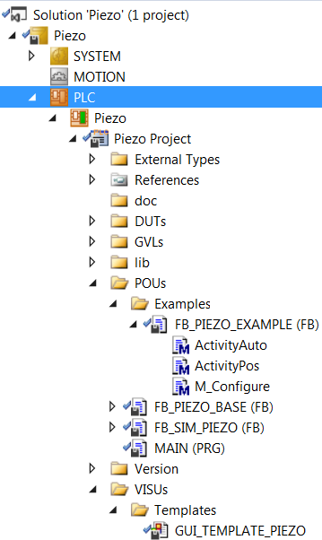
Piezo Library (piezo.library)
The piezo.library provides a generic PLC Piezo controller FB FB_PIEZO_BASE that has to be customised (extended) by the user. Up to three output control signals of type INT are supported (configurable). The example FB called FB_PIEZO_EXAMPLE shows how this customisation could be done.
The figure below shows what is delivered in the library.
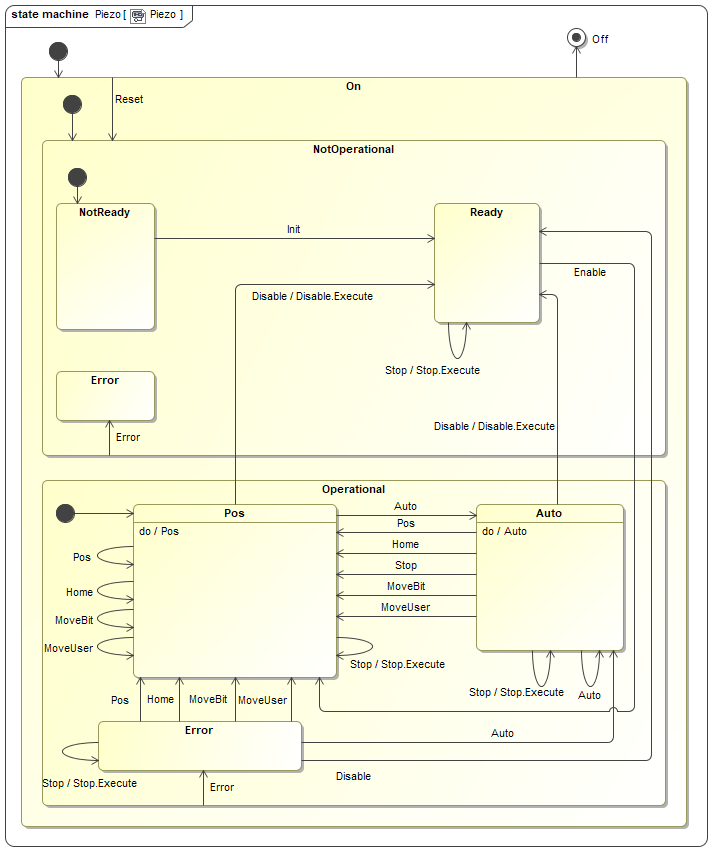
State Machine
The state machine of the piezo controller is shown below. The main operational states are Pos (stationary) and Auto (user-defined closed loop).
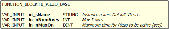
Input parameters
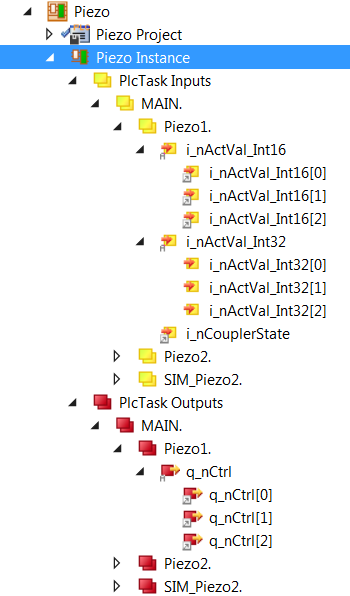
Signal Mapping
The figure below shows the TwinCAT view of the FB_PIEZO_BASE I/O variables that are available for mapping to physical signals, i.e. ports of I/O terminals.
There are two arrays for the feedback signals, one of type INT and the other one of type DINT. Any of them can be used in the customised application. There is an array for the control output signals of type INT.
The table below describes each mapping variable.
Variable |
Port Type |
Optional Mapping |
Description |
|---|---|---|---|
i_nCouplerState |
UINT |
No |
Mapped to the ‘state’ of the coupler that hosts I/O terminals. If the terminals span over more than one coupler, it is recommended to select the ‘state’ of the last coupler that hosts a lamp signal. |
i_nActVal_Int16 |
INT |
Yes |
Array [0..2] of feedback signals of type INT |
i_nActVal_Int32 |
DINT |
Yes |
Array [0..2] of feedback signals of type DINT |
q_nCtrl |
INT |
No |
Array [0..2] of control output signals of type INT |
GUI Template
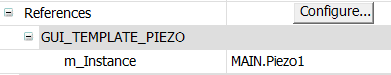
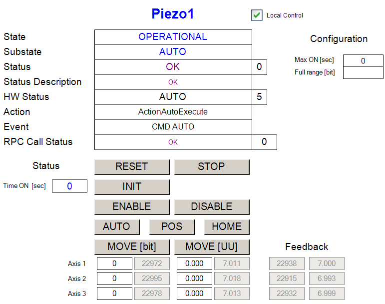
The piezo.library provides a template GUI called GUI_TEMPLATE_PIEZO for the control of Piezo devices. Applications can easily deploy an instance of this GUI by setting the GUI references to a particular instance, as shown below.
Piezo specific RPC Methods
Method |
Description |
|---|---|
RPC_Auto |
Start Automatic Loop. The user has to overload method ActivityAuto() |
RPC_Home |
Move piezos to Home position |
RPC_MoveBit |
Move piezos to positions given in [bit] |
RPC_MoveUser |
Move piezos to positions given in user units [UU] |
RPC_Pos |
Keep the piezos where they are (default behaviour). This might mean to stop the Auto loop. The user can overload this method. |
Piezo Simulator
The function block FB_SIM_PIEZO implements the piezo simulator on the PLC. The FB doesn’t have any input parameter. The simulator takes the real piezo device control outputs and generate its own feedback output signals by adding sine wave offsets. The simulator output feedback is mapped to the feedback inputs of the simulated device. The sine wave is fully configurable (amplitude and cycle period).
Piezo Simulator RPC Methods
Method |
Description |
|---|---|
RPC_ResetConfig |
Reset simulator configuration to its default. |
RPC_SetCouplerState |
Set coupler state. Any value other than 8 would cause a failure of the simulated device. |
RPC_SetMaxError |
Set Maximal Simulated feedback offset [bit] and the Period for complete sine wave offset cycle [msec] |
Simulator Mapping

Sample Code
The following code represent a real Piezo controller (Piezo1) and a piezo controller (Piezo2) that is connected to a simulator (SIM_Piezo2). The mapping is shown in the Simulator Mapping section.
PROGRAM MAIN
VAR

        {attribute 'OPC.UA.DA':='1'}
        Piezo1:     FB_PIEZO_EXAMPLE;       // Piezo #1
        {attribute 'OPC.UA.DA':='1'}
        Piezo2:     FB_PIEZO_EXAMPLE;       // Piezo #2

        {attribute 'OPC.UA.DA':='1'}
        SIM_Piezo2: FB_SIM_PIEZO;           // Simulator for Piezo #2

END_VAR
Piezo1(in_sName:='Piezo1', in_nNumAxes:=3);

Piezo2(in_sName:='Piezo2', in_nNumAxes:=3);

SIM_Piezo2();
Actuator Library (actuator.library)
FB_ACTUATOR is the TwinCAT PLC Function Block for the low level control of actuators. The most common use of this FB is for power control.
The functionality is very similar to the one of FB_LAMP with an important difference that the HW state (On/Off) of the actuator is not affected by the state change of the controller (NOT_OP/OPERATIONAL). The HW state can only be changed in OPERATIONAL state using ON and OFF commands. An actuator can be configured to go ON on PLC reboot or on RESET of the controller. The configuration is set with the input parameter in_bInitialState.
State Machine
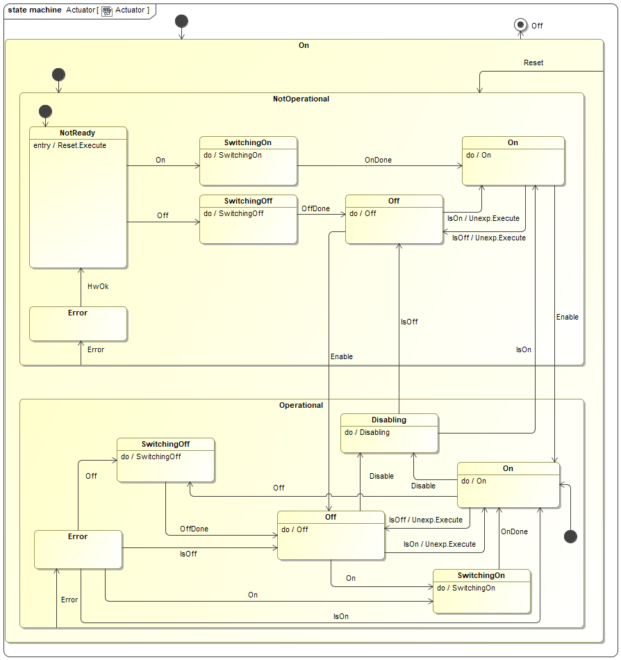
The state machine of the actuator controller is shown below. The main operational states are On, Off, Switching On and Switching Off.
Input parameters

Signal Mapping
The figure below shows the TwinCAT view of the FB_ACTUATOR I/O variables that are available for mapping to physical signals, i.e. ports of I/O terminals.

Example of FB_ACTUATOR input/output signals.
The table below describes each mapping variable.
Variable |
Port Type |
Optional Mapping |
Description |
|---|---|---|---|
i_nCouplerState |
UINT |
No |
Mapped to the ‘state’ of the coupler that hosts I/O terminals. If the terminals span over more than one coupler, it is recommended to select the ‘state’ of the last coupler that hosts an actuator signal. |
i_bOn |
Digital In |
No |
Mapped to the Actuator status (ON/OFF) digital input signal. |
i_nOn |
Analog In |
Yes |
Analog feedback signal. Has to be mapped only if analog feedback is used. |
q_bSwitch |
Digital Out |
No |
Mapped to the Actuator control digital output signal. |
GUI Template
The Actuator Library provides a template GUI to control instances of FB_ACTUATOR. Applications can easily deploy an instance of this GUI to control their own actuator function blocks by setting the GUI references to the particular instance of FB_ACTUATOR, as shown below.

Instantiation of GUI_TEMPLATE_ACTUATOR for Actuator001

FB_ACTUATOR HMI for Local Control.
Actuator specific RPC Methods
RPC_Off() Turn actuator OFF
RPC_On() Turn actuator ON
Actuator Simulator
The function block FB_SIM_ACTUATOR implements the actuator simulator on the PLC. The simulator has the address of the actuator instance as the only input parameter. The following code shows how the simulator is declared and executed:
Declaration:
{attribute 'OPC.UA.DA':='1'}
Actuator001:        FB_ACTUATOR;    // Simulated power

{attribute 'OPC.UA.DA':='1'}
SIM_Actuator001:    FB_SIM_ACTUATOR;
Execution:
// Actuator001 configuration:
// - Go to  OPERATIONAL on PLC reboot
// - Initial state is OFF
Actuator001(in_sName:='Actuator001', in_bAutoOp:=TRUE,in_bInitialState:=FALSE);

// Actuator001 Simulator
SIM_Actuator001(ptrDev:=ADR(Actuator001));
Simulator Mapping

Simulator RPC Methods

Creating PLC Applications with MakeTcProject Utility
A Windows utility called MakeTcProject.exe is provided for automatic creation of TwinCAT projects with a selectable number of available FCF controllers. For example, with this utility the user could automatically build a PLC application for four lamps, three shutters, two motors and two actuators. The utility generates a fully operational project that includes the selected number of devices/controllers and their simulators, i.e. every device is simulated at the PLC level. Without any modification, the project can directly run on the development PC in Local mode or be deployed to a PLC.
The utility is recommended to be used as the starting point for creating PLC applications since it creates all necessary PLC tasks, Function Block instances, GUIs and establishes I/O links. The utility is also very useful at early stages of instrument projects when HW is not yet available, since it makes it possible to test the complete control system as if the HW were present. Once a particular piece of HW gets available, the corresponding simulator part should be removed from the project and the function block I/O variables linked to the real system I/O instead of the simulator.
Note
Important note: The generated PLC application uses PLC simulators, so it can run on both the PC in Local mode or on the PLC target without the need for any hardware. However, once the HW is available, the PLC signal mapping has to be adjusted accordingly. From the Device Manager point of view that runs on the WS, it believes that it controls the real HW.
The Windows executable MakeTcProject.exe is located in the <ifw-ll>/tools/twincat/makeTcProject directory, where <ifw-ll> is the directory on the Windows PC where the tar file of the component ifw-ll has been checked out from the ESO Gitlab site IFW-LL release 2.0.0. There is no need to install the executable but it is important to note that it has to be executed from this directory because it uses a relative path to find required resources. Note that MakeTcProject.exe is a Windows program and it has to be executed from the Command Prompt (cmd) application. The target PLC configuration is defined in the corresponding configuration file MakeTcProject.cfg that is also located in the <ifw-ll>/tools/twincat/makeTcProject directory.
The FCF PLC binaries (libraries and modules) are located in the SVN repository tag under http://svnhq9.hq.eso.org/p9/tags/EELT/ICS/PLC/2.0.0. The complete directory has to be checked out to a local directory on the TwinCAT development PC. Prior to building the PLC application, the MakeTcProject.exe utility installs the PLC binaries in the TwinCAT Library Repository from that directory.
Configuration File MakeTcProject.cfg
The configuration file sets all parameters needed by the utility, including the Visual Studio version, the location of PLC binaries, the TwinCAT output project name and the type and the number of controllers to include in the application.
The following table describes each entry in the configuration file.
Parameter |
Values |
Default |
Description |
|---|---|---|---|
VisualStudio |
2013, 2017, etc |
2013 |
Version of Visual Studio to use. This version has to be already installed. |
Binaries |
C:\Temp\PLC |
Directory where the PLC binaries are checked out. |
|
Project |
plcprj |
TwinCAT project name. |
|
Lamps |
0, 1, etc |
1 |
Number of Lamps to generate. |
Shutters |
0, 1, etc |
1 |
Number of Shutters to generate. |
Motors |
0, 1, etc |
1 |
Number of Motors to generate. |
Piezos |
0, 1, etc |
1 |
Number of Piezos to generate. |
Actuators |
0, 1, etc |
1 |
Number of Actuators to generate. |
ADC |
yes | no |
yes |
If yes, ADC instance will be generated. Note that an ADC instance includes two prism motors (mult-axis). |
DROT |
yes | no |
yes |
If yes, DROT instance will be generated. |
IODEV |
yes | no |
yes |
If yes, two example instances of IODEV will be generated, one for a sensor and one for an I/O device. |
Utility Specifics
Generated projects are saved in the C:\Temp\Solutions directory. It is not possible to change the destination directory.
The resulting PLC application is not optimized for the usage of CPU cores of multi-core CPUs. All PLC tasks are configured to run on Core0 and other cores, if exist, are not used. It is the responsibility of the user to optimize the PLC application by activating available isolated cores and moving tasks from one core to the other.
Generated instances of controllers/devices will be named <device>xxx, e.g. Motor001, Motor002, etc. The user will have to rename (refactor) them to, e.g. Filter1, Mirror1, etc.
There utility will generate only one GUI per controller type using the following convention: GUI_<device>001, e.g. GUI_Lamp001. The user will have to rename (refactor) them to, e.g. GUI_Neon, GUI_ThArg, etc.
Summary of Main Steps
The following is the summary of the required steps to build and customize the PLC application.
Retrieve the FCF SW from GIT and SVN repositories.
Edit file MakeTcProject.cfg to match the system configuration and the PLC project.
Build the PLC application.
Open the PLC application with TwinCAT, rebuild it and run it in Local mode on the PLC.
Refactor the PLC application by renaming the controller instances and GUIs.
Rebuild the PLC application and deploy it to the PLC.
Test the devices in PLC simulation.
Once the HW is available, scan the PLC HW and map the controller I/O signals to the real HW I/O.
In this example we assume the following:
VisualStudio 2013 is the version to be used for building the PLC application. The specified version, together with the Beckhoff TwinCAT SW has to be already installed on the Windows PC.
The tar file of the component ifw-ll has been checked out from the ESO Gitlab site and extracted into the D:\GIT\ifw-ll directory on the Windows PC, so the utility and the configuration file can be found in the D:\GIT\ifw-ll\tools\twincat\makeTcProject directory.
The PLC binaries are checked out from the SVN repository under http://svnhq9.hq.eso.org/p9/tags/EELT/ICS/PLC/2.0.0 into the C:\Temp\PLC directory.
Building PLC Application
This section describes, step-by-step, the process of building the PLC application.
The procedure is the following:
Check-out the IFW-LL release 2.0.0 tar file and extract it into the D:\GIT\ifw-ll directory on the Windows PC.
SVN check out the binaries tag http://svnhq9.hq.eso.org/p9/tags/EELT/ICS/PLC/2.0.0 to C:\Temp\PLC.
Edit file MakePlcProject.cfg in D:\GIT\ifw-ll\tools\twincat\makeTcProject and adjust the number of instances for each type of controller. The example below shows the default configuration - one of each controller.
D:\GIT\ifw-ll\tools\twincat\makeTcProject>type MakeTcProject.cfg
VisualStudio: 2013
Binaries: C:\Temp\PLC
Project: plcprj
Lamps: 1
Shutters: 1
Motors: 1
ADC: yes
DROT: yes
IODEV: yes
Piezos: 1
Actuators: 1
Open a cmd terminal and CD to the D:\GIT\ifw-ll\tools\twincat\makeTcProject directory.
Run MakeTcProject.exe. The created TwinCAT project will be saved in the C:\Temp\Solutions directory. The output will look like this:
D:\GIT\ifw-ll\tools\twincat\makeTcProject>MakeTcProject.exe
MakeTcProject $Id: Program.cs 332694 2020-05-20 21:22:51Z wpirani $
INFO:
Visual Studio = '2013'
Binaries = C:\Temp\PLC
Project = 'plcprj'
Motors = 1
Lamps = 1
Shutters = 1
DROT = True
ADC = True
IODev = True
Piezos = 1
Actuators = 1
Trying to lunch Visual Studio 2013...
Creating empty project...
Adding module trkParams with GUID {15952e35-5679-4d71-9f28-196df14bbd2e}
Adding module trkModule with GUID {6f6a340e-378a-4fe4-ab0d-f15c12dfef0c}
Populating project...
Adding libraries...
Copying required libraries to System repository...
        C:\Temp\PLC\Libraries\actuator.library
        C:\Temp\PLC\Libraries\IODev.library
        C:\Temp\PLC\Libraries\Lamp.library
        C:\Temp\PLC\Libraries\Motor.library
        C:\Temp\PLC\Libraries\Mudpi.library
        C:\Temp\PLC\Libraries\Piezo.library
        C:\Temp\PLC\Libraries\plctpl.library
        C:\Temp\PLC\Libraries\rsCommCommon.library
        C:\Temp\PLC\Libraries\rsCommSerial.library
        C:\Temp\PLC\Libraries\rsCommTcp.library
        C:\Temp\PLC\Libraries\rsCommTcpRt.library
        C:\Temp\PLC\Libraries\Shutter.library
        C:\Temp\PLC\Libraries\Switch.library
        C:\Temp\PLC\Libraries\timer.library
Adding required libraries to this project...
Importing VISUs...
Importing: GUI_CCS_SIM.TcVIS from ..\..\..\controllers\motor\Motor\VISUs\Tracking\
Importing: GUI_time_info.TcVIS from ..\..\..\controllers\timer\timer\timer\VISUs\
Importing: GUI_MA_ADC.TcVIS from ..\..\..\controllers\motor\Motor\VISUs\Tracking\
Importing: GUI_MA_DROT.TcVIS from ..\..\..\controllers\motor\Motor\VISUs\Tracking\
Importing: GUI_Lamp001.TcVIS from ..\..\..\controllers\lamp\Lamp\Lamp\VISUs\
Importing: GUI_Motor001_Cfg.TcVIS from ..\..\..\controllers\motor\Motor\VISUs\Motor\
Importing: GUI_Motor001_Ctrl.TcVIS from ..\..\..\controllers\motor\Motor\VISUs\Motor\
Importing: GUI_Shutter001.TcVIS from ..\..\..\controllers\shutter\Shutter\Shutter\VISUs\
Importing: GUI_IODev001.TcVIS from ..\..\..\controllers\ioDev\IODev\IODev\VISUs\
Importing: GUI_Piezo001.TcVIS from ..\..\..\controllers\piezo\Piezo\Piezo\VISUs\
Importing: GUI_Actuator001.TcVIS from ..\..\..\controllers\actuator\actuator\actuator\VISUs\
Fixing references for: C:\temp\Solutions\plcprj\plcprj\VISUs\GUI_CCS_SIM.TcVIS
Fixing references for: C:\temp\Solutions\plcprj\plcprj\VISUs\GUI_time_info.TcVIS
Fixing references for: C:\temp\Solutions\plcprj\plcprj\VISUs\GUI_MA_ADC.TcVIS
Fixing references for: C:\temp\Solutions\plcprj\plcprj\VISUs\GUI_MA_DROT.TcVIS
Fixing references for: C:\temp\Solutions\plcprj\plcprj\VISUs\GUI_Lamp001.TcVIS
Fixing references for: C:\temp\Solutions\plcprj\plcprj\VISUs\GUI_Motor001_Cfg.TcVIS
Fixing references for: C:\temp\Solutions\plcprj\plcprj\VISUs\GUI_Motor001_Ctrl.TcVIS
Fixing references for: C:\temp\Solutions\plcprj\plcprj\VISUs\GUI_Shutter001.TcVIS
Fixing references for: C:\temp\Solutions\plcprj\plcprj\VISUs\GUI_IODev001.TcVIS
Fixing references for: C:\temp\Solutions\plcprj\plcprj\VISUs\GUI_Piezo001.TcVIS
Fixing references for: C:\temp\Solutions\plcprj\plcprj\VISUs\GUI_Actuator001.TcVIS
Building project...
Linking variables...
Fixing C:\temp\Solutions\plcprj\plcprj\PlcTask.TcTTO...
All done!
Testing PLC Application on Windows PC
In this step, the PLC application is open with the TwinCAT IDE and the application is run on the development Windows PC in Local mode. Each device can be tested using the generated GUIs.
In the Windows Explorer, go to the C:\Temp\Solutions\plcprj directory and double-click on plcprj.sln. This will start the TwinCAT IDE and open the newly created project.
From the BUILD pull-down menu, click on Rebuild Solution.
From the TWINCAT pull-down menu, click on Activate Configuration. Confirm with ‘OK’. When asked “Restart TwinCAT System in Run Mode”, confirm with OK.
From the PLC pull-down menu, click on Login. Confirm with ‘OK’.
In the TwinCAT Solution Explorer window on the left, go to the VISUs directory and start the GUIs by double-clicking on each of them. Test each device.
Customizing PLC Application to match Instrument Project
In this step, the user has to rename (refactor) the instances of controllers/devices in order to match the Instrument SW configuration. Please note that the Refactor feature in the TwinCAT IDE is a very powerful, quick and safe tool for renaming all instances of a certain string in the PLC project.
For example, the following renaming will be done in the project:
Refactor Lamp001 to ThArg.
Refactor Motor001 to Filter1.
Refactor Actuator001 to CamPower.
Rename GUI_Lamp001 to GUI_ThArg.
etc, etc
PLC Application deployment to PLC
In this step, the PLC will be deployed to the real PLC with a given name and IP address. From the TwinCAT IDE, the user has to choose the target PLC system. This can be done only if the current target is Local.
The procedure is the following:
Logout by clicking on the PLC pull-down menu and selecting Logout.
Ensure that the current target system is <Local>.
Click on <Local> and select Choose Target System….
From the Choose Target System, select Search (Ethernet)….
In the Enter Host Name / IP field, write the PLC name or the IP and press Enter.
Select the PLC from the available list and press Add Route to connect to the PLC.
After the connection with the PLC has been established, the PLC application can be downloaded to the PLC and tested in simulation.
Once the HW is available, the I/O links with the simulators should be cleared and the mapping should be done with the real HW I/O instead. Unused simulators should be removed from the project.