Getting Started
Log-in
Login to a standard ELT machine.
IFW Software
If not yet done, retrieve and install the complete ICS Framework from the ESO RPMs repository. For more details, please have a look to the installation procedure here
You should create your software based on the provided template by following the procedure in the Getting Started guide here
This guide assumes you have followed all the steps in the above guide. The examples assume you selected
the instrument as tins, the INS component as fcs and the custom device as mirror. You can adapt the
configuration according to your needs.
Database Server
The present version of the Device Manager has adopted the CCS OLDB as the database engine to store run-time configuration (OLDB documentation).
Warning
This version is no longer compatible with old ELT development environments.
The OLDB service shall be running after following the installation procedure and general Getting Started: installation here guide here
The data is stored in the DB using a list of keyword/values. Each keyword has a hierarchical name that helps to idenfify its context, for instance the keys associated to a Device Manager start with the <server id> defined in the FCF configuration.
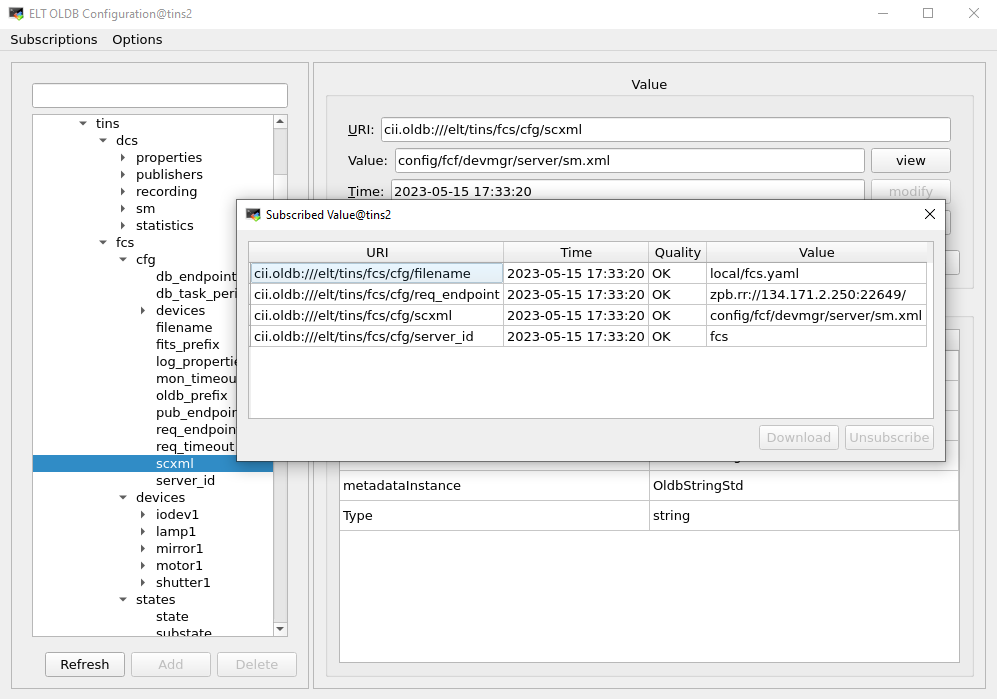
The ELT development environment provides a OLDB browser tool (oldbGui) that can be used to monitor the database keywords in an easy way similar to the ccseiDb tool in the VLT project.

OLDB browser tool screenshot showing Device Manager attributes.
oldbGui &
Note
The attributes will be populated only when the Device Manager server is started.
INS Configuration
The project template includes a sample of a FCF configuration. The generated directory contains a fully working waf project with a custom device to be used as starting point for the development. After executing the cookiecutter command with the provided template, you can build, install and deploy the provided example.
Please follow the instructions in the general Getting Started guide here
The Device Server requires a configuration file including all the
relevant information for the server. A pre-defined configuration has been created as part of the generation
process. This configuration includes four standard devices plus a the custom device.
Generated server configuration: <ins id>/resource/nomad/<component>.yml.tpl. This files contains the Nomad tags so it should not be used directly but through a nomad job command.
!cfg.include config/fcf/devmgr/definitions/server.yaml:

server: !cfg.type:FcfServer
    server_id       : '{{cookiecutter.component_name}}'

    req_endpoint    : "zpb.rr://{{ range service "${component}-req" }}{{ .Address }}:{{ .Port }}{{ end }}/"
    pub_endpoint    : "zpb.ps://{{ range service "${component}-pub" }}{{ .Address }}:{{ .Port }}{{ end }}/"

    db_timeout      : 2000
    scxml           : "config/fcf/devmgr/server/sm.xml"
    dictionaries    : ["dictionary/dit/stddid/primary.did.yaml", "dictionary/fcf/devmgr/server/fcf.did"]
    fits_prefix     : "INS1"
    log_properties  : "config/{{cookiecutter.component_name}}/server/log_properties.cfg"
    devices         : [
    {
    name: 'shutter1',
    type: Shutter,
    cfgfile: "local/shutter1.yaml"
    },
    {
    name: 'lamp1',
    type: Lamp,
    cfgfile: "local/lamp1.yaml"
    },
    {
    name: 'motor1',
    type: Motor,
    cfgfile: "local/motor1.yaml"
    },
    {
    name: 'iodev1',
    type: IODev,
    cfgfile: "local/iodev1.yaml"
    },
    {
    name: '{{cookiecutter.device_name}}1',
    type: {{cookiecutter.device_name|capitalize()}},
    cfgfile: "local/{{cookiecutter.device_name}}1.yaml"
    }
    ]
Note
This configuration is just an example and shall be adapted to the instrument specific needs.
Device Manager Logs
$ nomad alloc logs -job fcs
The output of the server shall be something like the following:
2023-05-15T19:35:43.669.559 INFO  Loaded successfully configuration file <local/fcs.yaml>
2023-05-15T19:35:43.669.580 INFO  Loading custom configuration
2023-05-15T19:35:43.669.593 INFO  FCF Version:  = <0.0.0>
2023-05-15T19:35:43.669.612 INFO  CfgFile - Devices: 5
2023-05-15T19:35:43.669.625 INFO  shutter1
2023-05-15T19:35:43.669.649 INFO  lamp1
2023-05-15T19:35:43.669.657 INFO  motor1
2023-05-15T19:35:43.669.664 INFO  iodev1
2023-05-15T19:35:43.669.670 INFO  mirror1
2023-05-15T19:35:43.669.792 INFO  Application fcsDevmgr started.
2023-05-15T19:35:43.671.313 INFO  PS Endpoint: zpb.ps://134.171.2.250:31227/std/status
2023-05-15T19:35:43.941.182 INFO  Succesfully connected to OLDB !
2023-05-15T19:35:43.941.224 INFO  Starting OLDB write thread...
2023-05-15T19:35:43.942.613 INFO  Loading config file:local/shutter1.yaml
2023-05-15T19:35:43.944.194 INFO  Configuration file has been loaded :local/shutter1.yaml
2023-05-15T19:35:43.946.294 INFO  Loading config file:local/lamp1.yaml
2023-05-15T19:35:43.947.459 INFO  Configuration file has been loaded :local/lamp1.yaml
2023-05-15T19:35:43.949.123 INFO  Loading config file:local/motor1.yaml
2023-05-15T19:35:43.951.380 INFO  Configuration file has been loaded :local/motor1.yaml
2023-05-15T19:35:43.951.455 INFO  [motor1] tolerance: 1
2023-05-15T19:35:43.951.463 INFO  [motor1] reading name position:motor1
2023-05-15T19:35:43.951.472 INFO  [motor1] name positions:2
...
Note
The server can be started with option -l ERROR to remove the information logs.
Initialising the server
The client application can be used to send commands to the server from the command line:
$ fcfClient `geturi fcs-req` GetState ""
Note
geturi is an utility to compose the expected URI from the name of the registered Consul service.
The reply from the server shall be something like the following:
Idle/Operational/On/
Besides the above, you can also use the FCF CLI to interact with the server.
$ fcscli --name fcs-req
zpb.rr://134.171.2.250:24738
fcsSh> status
Note
The fcscli is a custom INS CLI provided in the template. It already contains the configuration to include the custom FCF python libraries.
Using the DeviceManager GUI (fcsGui)
Starting the GUI
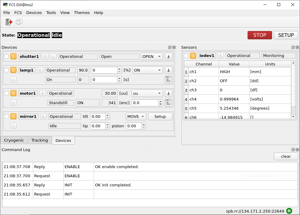
$ fcsGui --uri `geturi fcs-req` &
The sample GUI defines some sections to illustrate how developers can organize the various docking widgets. This is just an example that shall be adapted to the needs of each instrument.
Note
The first time the GUI is started, it might appear too small to display all the information from the device widgets. The user has to resize it and organize the docking widgets accordingly. It is recommended to stack all the dock windows together. This can be done using drag&drop from the docking title area.
Note
If you want to use another style, you can start the GUI with option –stylesheet-name or –stylesheet-file if you have your own style-sheet file. Since version 5.0.0 beta, you can also change the look and feel of the GUI from the Themes menu.
You can control the devices from the GUI, for instance by selecting the action OPEN or CLOSE from the shutter widget and then pressing Setup button.

Device Manager Engineering Graphical Interface.
Using the Motor Engineering GUI (fcfMotGui)
Starting the GUI
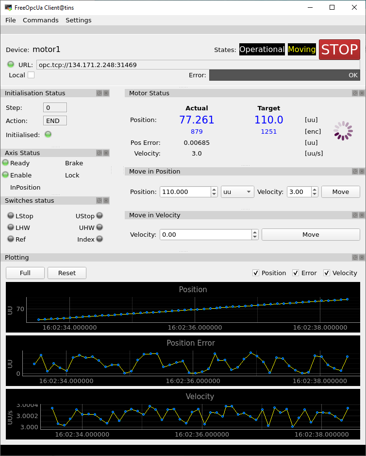
This GUI can be started from the command line or launched from the fcfGui by clicking with the mouse pointer over the small ‘gui’ button on each motor widget.
fcfMotGui -d motor1 -a opc.tcp://127.0.0.1:7578 -p MAIN.Motor1 &

Motor Engineering GUI.
Controlling Custom Device
Warning
The mirror device is a dummy device that is a showcase how to develop custom devices.
The custom device (mirror) includes a setup that triggers the execution of a custom RPC in the controller (simulator).
$ fcsSh> setup_json_string '[{"id": "mirror1", "param": { "mirror": {"action": "MOVE", "tip": 2.1, "tilt": 4.3}}}]'
Note
The client library will check the JSON string against the defined schema. If the validation is okay, it will send this JSON string to the server which it will pass it to the corresponding device to be processed.
Note
The same you can do from the custom GUI which provides a custom widget for this device.
The reply from the server shall be something like the following:
2021-04-20T13:01:55.551216   INFO Started SETUP command
2021-04-20T13:01:55.551443   INFO Processing Setup command ...
2021-04-20T13:01:55.551506   INFO ID: mirror1
2021-04-20T13:01:55.551621   INFO Setup buffer: {"action": "MOVE", "tip": 2.1, "tilt": 4.3}
2021-04-20T13:01:55.552321   INFO Action: MOVE
2021-04-20T13:01:55.552358   INFO Tip: 2.1
2021-04-20T13:01:55.552365   INFO Tilt: 4.3
2021-04-20T13:01:55.552373   INFO [mirror1] Executing RPC_PING ...
2021-04-20T13:01:55.553805   INFO [mirror1] Successful call of Mirror ping:
Note
To see the specific logs from the custom device, the logging level shall be specified for that device, e.g. setloglevel INFO,mirror
Forcing a Syntax Error
The custom device defines a sample schema where parameters tip and tilt are mandatory. If a setup is sent with a missing required parameter, this will be detected when validating against the schema, see below.
$ fcsSh> setup_json_string '[{"id": "mirror1", "param": { "mirror": {"action": "MOVE", "tip": 3}}}]'
'tilt' is a required property

Failed validating 'required' in schema['items']['properties']['param']['properties']['mirror']:
    {'properties': {'action': {'description': 'Mirror action.',
                               'enum': ['MOVE'],
                               'type': 'string'},
                    'piston': {'description': 'piston.', 'type': 'number'},
                    'tilt': {'description': 'tilt.', 'type': 'number'},
                    'tip': {'description': 'tip.', 'type': 'number'}},
     'required': ['action', 'tip', 'tilt'],
     'type': 'object'}

On instance[0]['param']['mirror']:
    {'action': 'MOVE', 'tip': 3}
JSON data not valid !
ERROR: something went wrong, setup buffer not modified
...
Working with a PLC
The following steps can be done to use the server configuration that was generated with controllers running in a PLC.
Note
The provided PLC project includes the corresponding simulators so hardware is not needed only a bare PLC. All the mapping is pre-configured and the PLC code is generated to match the server configuration (only the three standard devices).
Requirements
PLC available with required version of TwinCAT run-time and OPC-UA Server.
Windows development environment with required TwinCAT software installed.
All ESO PLC libraries installed in the Windows development environment.
Load the PLC Project
From a Visual Studio load the PLC project generated. The project can be found in fcs1/LCS/plcprj1.
Select Target System
Select the target system, this is the PLC that you want to use.
Build the PLC Project
If you have errors, make sure you have all ESO libraries installed.
Activate Configuration
This active the project configuration and restart the OPC-UA Server in the PLC.
Login to the target system.
This will download the code to the PLC.
Update the configuration of each device with the corresponding PLC address (IP).
!cfg.include config/fcf/devmgr/definitions/lamp.yaml:

lamp1: !cfg.type:Lamp
identifier: PLC1                             # OPCUA Object Identifier
prefix: MAIN.Lamp1                           # OPCUA attribute prefix
simulated: true
dev_endpoint: undefined                                      # To be set if a PLC is available
sim_endpoint: opc.tcp://{{ range service "lamp1sim" }}{{ .Address }}:{{ .Port }}{{ end }}
fits_prefix: "LAMP1"
Stop the simulation for the devices
$ fcfClient `geturi fcs-req` Reset ""
$ fcfClient `geturi fcs-req` StopSim "lamp1, shutter1, motor1"
Note
By changing the flag simulated to false in the device configuration it is possible to make this change persistent.
Set the server to operational state
$ fcfClient `geturi fcs-req` Init ""
$ fcfClient `geturi fcs-req` Enable ""
You can now operate the server with devices connected to the PLC controllers.
Stopping the Software
Stopping the GUI
The menu File has an option Quit. Please select this option if you want to stop properly the GUIs.
Stopping the Software
You can use the startup/shutdown script provide to stop the whole software. For more details please check the general Getting Started guide here