Device Simulator
The FCF SDK provides a small Python base application to implement Device Simulators on the WS, for short: DevSim. These Device Simulators emulate the PLC sufficiently well to be able to carry out the basic operations of the device. This makes it possible to carry out a integration test of the instrument software, without the availability of a ‘physical’ PLC or HW. This is useful, e.g. for autonomous tests, running during in Jenkins, and, of course, during development, where it may be more efficient to test/debug against a local process, rather than a PLC; maybe a PLC is not even always available.
The FCF Device Simulators implement the same state machine as is implemented on the PLC. Moreover the OPC UA interface (namespace), is the same, at least for what concerns the nodes, essential for controlling and monitoring the PLC device from the FCF Device Manager.
The Device Simulators load the SCXML state machine model and the OPC UA namespace profile at start-up and configures themselves accordingly.
It is possible to implement customised business logic for each Device Simulator, to achieve a simulation, accurate enough to do the development and test of the WS Device Manager.
For each Special Device, implemented for an instrument, an FCF Device Simulator shall be provided, in addition to the WS Device Manager and PLC device code.
It may be useful, to start the implementation of a new device by implementing first the Device Simulator, and then use this during the implementation of the Device Manager, because it is easier to control a local application than an application running on a PLC and some device operations may be executed faster by the Device Simulator compared to executing them on the PLC.
The following standard Device Simulators are provided:
Actuator
ADC
DROT
IO Device
Lamp
Motor
Piezo
Shutter
If support for new types of devices is added, the associated Device Simulators will be provided.
Device Simulator - Command Line Options
A Device Simulator accepts the following command line options (example):
$ fcfDevsimShutter --help
usage: fcfDevsimShutter [-h] --port PORT --cfg CFG [--use-ext-ip]
                        [--log-level LOG_LEVEL {CRITICAL,ERROR,WARNING,INFO,DEBUG}]
                        [--log-file LOG_FILE] [--verbose]
                        [--server-name SERVER_NAME]

Device Workstation Simulator

optional arguments:
  -h, --help            show this help message and exit
  --port PORT           server port number
  --cfg CFG             configuration
  --use-ext-ip          use the external IP address of deployment host
  --log-level LOG_LEVEL
                        set log level (CRITICAL, ERROR, WARNING, INFO, DEBUG)
  --log-file LOG_FILE   log output file
  --verbose             output log on stdout
  --server-name SERVER_NAME
                        server name
Option: “cfg”:
YAML based configuration. The general part and specific part for each DevSim is described below.
Option: “use-ext-ip”:
By default, a Device Simulator uses the loop-back IP address (127.0.0.1). This means that is it only possible to reach it from within the local host. To make the Device Simulator available on the network, use this option to make it serve on the external IP address.
Option: “server-name”:
When generating the OPC UA XML profile on-the-fly, this option can be used to specify the name of the device, as it will be defined in the OPC UA namespace.
Device Simulator - Base Application
A Device Simulator is derived from the base class fcf_devsim_lib.device_simulator_base.DeviceSimulatorBase.
At this point, there is no way to generate the Python source files for a Device Simulators, so the files must be prepared by hand. It is suggested to copy the source files of one of the existing Device Simulators, and adapt them.
As example, the Lamp Device Simulator could be used. It is structured such that there is a library part, which could be re-used to implement other Device Simulators, with similar properties and the specific part, which is also the deployment module:
Generation of the SCXML State Machine Model
At this point in time, there is no way to share the same SXCML definition between the PLC and the associated DevSim. The SCXML state chart can be generated from the MagicDraw state machine chart, in which the proper COMODO stereotypes have been applied. For instructions for how to create the SCXML definition, using MagicDraw and COMODO, consult the RAD User Manual. Alternatively, the SCXML state chart document, can be created by hand, by means of a text editor or an XML editor. An example of the SCXML chart for the Lamp Device can be accessed here (generated from the MagicDraw model, using COMODO).
Generation of the OPC UA Namespace Profile
To facilitate generating the OPC UA XML namespace profile, a simpler and more compact format has been defined, based on YAML. An example of such a (source) YAML Namespace Definition can be accessed here: Standard Lamp Device YAML Namespace Definition.
Although the format of the YAML Namespace Definition is self-explicatory, here a few comments:
Left/right Columns:
The right column as an ‘internal name’, which may be used internally in the implementation of the Device Simulator code, but not necesarily. The right column is the name in the PLC namespace, the HW address. It is possible to define a specific data type for a name, by adding it in parentheses after the name, e.g. “StatCounter: stat.nCounter(UInt32)” (see list of supported types below). Default mapping of data types:
“b<name>” -> Boolean.
“n<name>” -> Int32.
“lr<name>” -> Float.
“s<name>” -> String.
The complete path is created by prepending “MAIN.” + <device name>, e.g. “Lamp1” + the HW address. An example of a complete name, as generated in the OPC UA namespace profile is, e.g.:
“ns=4;s=MAIN.Shutter1.stat.sStatus”
The “ns=4” indicates OPC UA namespace 4. For the moment, the convention is to use namespace 4. The “s=” that it is a string node ID, as opposed to an integer node ID. The “MAIN” is a convention, decided for the ELT ICS PLC code. Both namespace and the “MAIN” prefix may be made configurable, if necessary.
RPC Method Calls:
RPC method calls are defined as:
Rpc<Operation>: rpc.<Operation>([I:<Variable>(<type>)][,] O:<Variable>(<type>)])
whereby “I:” means input variable and “O:”, imaginatively, output value. The following types are supported:
Boolean
SByte
Byte
Int16
UInt16
Int32
UInt32
Int64
UInt64
Float
Double
String
DateTime
ByteString
The “coreGenOpcuaProfile” tool, is invoked as follows on the YAML Namespace Definition:
$ coreGenOpcuaProfile --device Shutter3 --name-mapping shutte.namespace.yaml
<?xml version="1.0" encoding="utf-8"?>
<UANodeSet xmlns:xsi="http://www.w3.org/2001/XMLSchema-instance"
           xmlns:uax="http://opcfoundation.org/UA/2008/02/Types.xsd"
           xmlns="http://opcfoundation.org/UA/2011/03/UANodeSet.xsd"
           xmlns:xsd="http://www.w3.org/2001/XMLSchema">

  <NamespaceUris>
    <Uri>http://www.eso.org/xmlShutter3/</Uri>
  </NamespaceUris>

  <UAObject NodeId="ns=1;s=PLC1" BrowseName="1:PLC1">
    <DisplayName>PLC1</DisplayName>
    <References>
      <Reference ReferenceType="HasTypeDefinition">i=58</Reference>
      <Reference ReferenceType="Organizes">ns=4;i=20737</Reference>
      <Reference ReferenceType="Organizes" IsForward="false">i=85</Reference>
    </References>
  </UAObject>
  ...
The output can be piped into a file, used as part of the configuration for the Device Simulator.
Note
DevSim provides a mechanism to generate the OPC UA namespace on-the-fly, in memory, directly from the source YAML definition. This is the recommended way of achieving the OPC UA namespace to automatically use the latest version and to avoid one configuration file (of which there are many…).
Example
$ fcfDevsimShutter --port 7677 --cfg config/fcf/devsim/shutter/shutter1.cfg.yaml --use-ext-ip --log-level DEBUG --verbose
2018-12-04 12:31:52.821:INFO:DevSim:MainThread:deviceSimulatorBase:557:execute: Setting up OPC UA server ...
Listening on 134.171.2.213:7577
2018-12-04 12:31:54.411:INFO:DevSim:MainThread:deviceSimulatorBase:567:execute: Setting up OPC UA server - done
2018-12-04 12:31:54.411:INFO:DevSim:MainThread:deviceSimulatorBase:574:execute: Loading configuration: fcf/devsim/devsimShutter/shutter1.yaml
2018-12-04 12:31:54.413:INFO:DevSim:MainThread:deviceSimulatorBase:578:execute: Loading OPC UA namespace definition: fcf/devsim/devsimShutter/shutter1Namespace.xml
2018-12-04 12:31:54.484:INFO:DevSim:MainThread:deviceSimulatorBase:582:execute: Parsing OPC UA node info
2018-12-04 12:31:54.639:INFO:DevSim:MainThread:deviceSimulatorBase:442:set_node_permissions_: Setting node permissions
2018-12-04 12:31:54.667:INFO:DevSim:MainThread:deviceSimulatorBase:454:install_data_ch_subscr_: Installing data change subscription handlers
2018-12-04 12:31:54.670:INFO:DevSim:MainThread:deviceSimulatorBase:464:install_rpc_methods_: Installing RPC method handlers
2018-12-04 12:31:54.670:INFO:DevSim:MainThread:deviceSimulatorBase:472:install_rpc_methods_: Installing RPC method handler for: self.RPC_GetNamespace
...
2018-12-04 12:31:54.673:INFO:DevSim:MainThread:deviceSimulatorBase:472:install_rpc_methods_: Installing RPC method handler for: self.RPC_Init
2018-12-04 12:31:54.673:INFO:DevSim:MainThread:deviceSimulatorBase:499:gen_opcua_state_node_ids_: Generating OPC UA state machine node IDs
2018-12-04 12:31:54.673:INFO:DevSim:MainThread:deviceSimulatorBase:145:init_device_parameters_: Initializing device parameters
2018-12-04 12:31:54.676:INFO:DevSim:MainThread:deviceSimulatorBase:593:execute: SCXML state machine model: fcf/devsim/devsimShutter/scxmlShutter.xml
2018-12-04 12:31:54.676:INFO:DevSim:MainThread:stateMachine:62:__init__: Loading SCXML model: fcf/devsim/devsimShutter/scxmlShutter.xml
2018-12-04 12:31:54.682:INFO:DevSim:MainThread:stateMachine:73:__init__: Status:
2018-12-04 12:31:54.682:INFO:DevSim:MainThread:deviceSimulatorBase:598:execute: Serving ...
2018-12-04 12:31:54.683:INFO:DevSim:MainThread:stateMachine:86:run: Starting execution of /home/jknudstr/ROOTS/INTROOT_eltdev26/resource/config/fcf/devsim/devsimShutter/scxmlShutter.xml
2018-12-04 12:31:54.685:INFO:DevSim:MainThread:stateMachine:91:run: Status: On On::NotOperational On::NotOperational::NotReady
After generating the SCXML definition and OPC UA XML Profile, it is possible to start up the Device Server and connect to the Device Simulator OPC UA server and execute e.g. the provided RPC calls and read/write variables, e.g.:
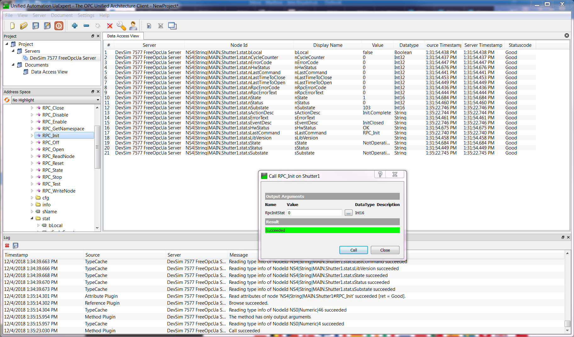
Shutter Device Namespace in UaExpert
Device Simulators for Standard Devices
This section provides specific details about the various Device Simulators provided for Standard Devices.
Since the Device Simulators are used to emulate the PLC Controllers, they implement the same behavior and therefore, their behavior is described in the PLC section of the FCF user manual and not repeated here. Here only specific properties of the Device Simulators are mentioned.
The following common configuration parameters are supported by all Device Simulators:
Parameter |
Type |
Description |
|---|---|---|
server_name |
String |
Name of device, e.g. “Lamp1”. Needed if the OPC UA namespace is generated from the OPC UA namespace source YAML document. |
opcua_profile |
String |
If using the on-the-fly generation of the OPC UA XML profile, this shall refer to the YAML representation of the XML profile. Otherwise it shall refer to the XML OPC UA profile. When using the on-the-fly generation for Standard Devices, it can normally be left out. |
state_machine_scxml |
String |
SCXML definition for the state machine engine. |
auto_enter_op |
Boolean |
Enter Operational State automatically when starting up. Not supported by all device simulators. |
local_mode |
Boolean |
Device simulator will emulate Localo Mode at start-up if True. |
update_frequency |
Float |
Frequency for the internal simulation loop (thread) in Hz. Default value is 10 Hz. |
sim_acceleration |
Float |
Factor, which can be used to tune the execution speed of actions in the Device Simulator, globally. |
sim_init_time |
Float |
Delay time applied during initialisation [s]. |
sim_delay |
Float |
General delay that can be applied when a delay is needed to make the simulation more realistic [s]. |
Note
In general the Device Simulators do not support ‘engineering mode’, but are mostly dedicated for the ‘common usage’, e.g. from Sequencer Templates and standard operation of the instrument software. This means that some ‘low level/engineering parameters’ and RPC calls may not supported.
Actuator Device Simulator
The state machine of the Actuator Device Simulator is the same as for the (Standard PLC Actuator Device).
The Actuator Device Simulator defines the following configuration parameters:
Parameter |
Type |
Description |
|---|---|---|
initial_state |
Boolean |
Initial state to assume after enabling the device (True = Open). |
ADC Device Simulator
The state machine of the ADC Device Simulator is the same as for the (Standard PLC ADC Device (tracking devices)).
The ADC Device Simulator defines the following configuration parameters:
Parameter |
Type |
Description |
|---|---|---|
cfg_motor1 |
String |
Configuration for the Motor DevSim for axis 1, e.g. “config/fcf/devsim/adc/adc1Motor1.cfg.yaml”. |
cfg_motor2 |
String |
Configuration for the Motor DevSim for axis 2. |
motor1_step |
Float |
Factor applied when calculating the next position for axis 1 for each simulated cycle of the ADC. The higher this factor, the faster the motor moves. |
motor2_step |
Float |
Factor applied when calculating the next position for axis 2 for each simulated cycle of the ADC. The higher this factor, the faster the motor moves. |
default_velocity |
Float |
Default velocity to apply to the internal motor axes [UU/s]. |
Note
The ADC Device Simulator does not support ‘engineering mode’ and can therefore not be used together with the FCF Python Motor GUI (“pymotgui”). In particular, the following RPC calls are not supported: RPC_MoveAbs, RPC_MoveAngle, RPC_MoveRel, RPC_MoveVel.
DROT Device Simulator
The state machine of the DROT Device Simulator is the same as for the (Standard PLC DROT Device (tracking devices)).
The DROT Device Simulator defines the following configuration parameters:
Parameter |
Type |
Description |
|---|---|---|
cfg_motor |
String |
Configuration for the Motor DevSim for internally controlled axis, e.g. “config/fcf/devsim/drot/drot1Motor.cfg.yaml”. |
motor_step |
Float |
Factor applied when calculating the next position for axis for each simulated cycle of the DROT. The higher this factor, the faster the motor moves. |
default_velocity |
Float |
Default velocity to apply to the internal motor axis [UU/s]. |
Note
The DROT Device Simulator does not support ‘engineering mode’ and can therefore not be used together with the FCF Python Motor GUI (“pymotgui”). In particular, the following RPC calls are not supported: RPC_MoveAbs, RPC_MoveAngle, RPC_MoveRel, RPC_MoveVel.
I/O Device Simulator
The I/O Device Simulator defines the following configuration parameters:
Parameter |
Type |
Description |
|---|---|---|
di<i>_value |
Boolean |
Initial or static value of signal of given channel. |
di<i>_function |
String |
Function, with parameters to be invoked. For now only a square wave generator is provided “di_square_wave(period hi[s], period lo[s])”. |
ai<i>_value |
Double |
Initial or static user value of signal of given channel. |
ai<i>_function |
String |
Function, with parameters to be invoked. For now only a sine wave generator is provided “ai_sine_wave(period[s], scale, offset)”. |
ii<i>_value |
Integer |
Initial or static user value of signal of given channel. |
ii<i>_function |
String |
Function, with parameters to be invoked. For now only a sine wave generator is provided “ii_sine_wave(period[s], scale, offset)”. |
Note: More simulation functions may be added on request. A future extension may be to allow user provided simulation function on a plug-in basis.
Lamp Device Simulator
The state machine of the Lamp Device Simulator is the same as for the (Standard PLC Lamp Device).
The Lamp Device Simulator defines the following configuration parameters:
Parameter |
Type |
Description |
|---|---|---|
sim_init_time |
Float |
Time to spend for the initialisation [s]. |
initial_state |
Boolean |
Initial state to assume after enabling the device (True = On). |
max_on |
Float |
Maximum time the lamp is allowed to remain switched on [s]. |
warm_up |
Float |
Time spent for the warm-up phase [s]. |
cool_down |
Float |
Time to spend for the cool-down [s]. |
Motor Device Simulator
The state machine of the Motor Device Simulator is the same as for the (Standard PLC Motor Device).
The Motor Device Simulator defines the following configuration parameters:
Parameter |
Type |
Description |
|---|---|---|
velocity_error |
Float |
Simulated error in % to be applied to the simulated velocity. |
sim_pos_error |
Float |
Simulated positioning error in % to be applied to the simulated position. |
sim_tolerance |
Float |
Tolerance to apply for considering simuilated position on target [UU]. |
simulated_start_pos |
Float |
Start position of motor after start-up of application. |
scale_factor |
Float |
Scale factor to apply for converting between UU and encoder values [UU/enc] |
min_position |
Float |
Minimum position [UU]. |
max_position |
Float |
Maximum position [UU]. |
timeout_init |
Float |
Timeout applied during initialisation [s]. |
timeout_move |
Float |
Timeout applied while moving simulated axis [s]. |
timeout_switch |
Float |
Timeout applied while moving simulated axis [s]. |
disable_after_move |
Boolean |
Disable the current on the simulated axis after completion of a movement. |
default_velocity |
Float |
Default velocity to apply, e.g. during initialisation [UU/s]. |
Piezo Device Simulator
The state machine of the Piezo Device Simulator is the same as for the (Standard PLC Piezo Device).
The Piezo Device Simulator defines the following configuration parameters:
Parameter |
Type |
Description |
|---|---|---|
initial_state |
Boolean |
Initial state to assume after enabling the device (True = Open). |
Shutter Device Simulator
The state machine of the Shutter Device Simulator is the same as for the (Standard PLC Shutter Device).
The Shutter Device Simulator defines the following configuration parameters:
Parameter |
Type |
Description |
|---|---|---|
initial_state |
Boolean |
Initial state to assume after enabling the device (True = Open). |
Developing a Device Simulator
The steps to implement a Device Simulator is as follows:
Generate the code of the Device Simulator from the template provided by FCF DevSim (see instructions below).
Define the state machine, generate the SCXML state chart document (see instructions above).
Define the namespace and OPC UA profile for the Device Simulator (see instructions above).
Adapt the code generated in step 1. according to the specific Device Simulator state machine and business logic (see instructions below).
Implement the necssary integration test cases to verify the basic functioning of the Device Simulator.
Note, it is important that the Device Simulator developed, emulates the PLC Controller relatively well for it to have a realistic behaviour.
It may not be necessary to implement all features of the PLC Controller, but the features needed to be able to execute the instrument integration tests, and to execute the Templates, both in simulation mode, without the availability of any hardware, shall be provided by the Device Simulator.
Generate the Code of the Device Simulator
The steps to generate the basic code are shown below. After generating the code, it will be necessary to adapt the specific code manually. The template provided is based on the Lamp Device Simulator described elsewhere in this document. After having generated the code for the new Device Simulator, a new instance of the Lamp Device Simulator is obtained as starting point for the development.
The steps to generate the basic code for the new Device Simulator are:
Enter the folder in the instrument source tree where the Device Simulator WTOOLS module shall be located.
Invoke Cookiecutter on the DevSim template.
Add the new Device Simulator module in the “wscript” file, found at the same level, if needed.
Build and install the instrument software.
Execute the generated Device Simulator.
Connect with an OPC UA client, e.g. UA Expert to verify that the Device Simulator is functioning properly.
In the following a live example of how to generate the code, is shown.
$ cookiecutter <path to ifw-hl>/ifw-fcf/devsim/templates/devsim_tpl/
device_name [device]: mydev
package_name [pkg]: mypkg
device_description [This the description of my device]: This is a test Device Simulator

$ find mydev/
mydev/
mydev/resource
mydev/resource/config
mydev/resource/config/mypkg
mydev/resource/config/mypkg/devsim
mydev/resource/config/mypkg/devsim/mydev
mydev/resource/config/mypkg/devsim/mydev/mydev.namespace.yaml
mydev/resource/config/mypkg/devsim/mydev/mydev.scxml.xml
mydev/resource/config/mypkg/devsim/mydev/mydev1.cfg.yaml
mydev/resource/config/mypkg/devsim/mydev/mydev.schema.yaml
mydev/src
mydev/src/mypkg
mydev/src/mypkg/devsim
mydev/src/mypkg/devsim/mydev
mydev/src/mypkg/devsim/mydev/__init__.py
mydev/src/mypkg/devsim/mydev/defines.py
mydev/src/mypkg/devsim/mydev/mydev.py
mydev/src/mypkgDevsimMydev.py
mydev/wscript

# Add "mydev" in the "wscript" file at the same level as the "mydev" module.

$ mypkgDevsimMydev --port 7777 --cfg config/mypkg/devsim/mydev/mydev1.cfg.yaml --use-ext-ip --log-level INFO --verbose
2023-05-19T12:29:03.782:INFO:SmOpcUaSrv:MainThread:serverbase:837:execute_int: Setting up OPC UA server ...
2023-05-19T12:29:05.599:INFO:SmOpcUaSrv:MainThread:serverbase:853:execute_int: Setting up OPC UA server - done
2023-05-19T12:29:05.599:INFO:SmOpcUaSrv:MainThread:serverbase:145:load: Loading configuration: config/mypkg/devsim/mydev/mydev1.cfg.yaml
2023-05-19T12:29:05.628:INFO:SmOpcUaSrv:MainThread:serverbase:148:load: Loaded configuration: config/mypkg/devsim/mydev/mydev1.cfg.yaml
2023-05-19T12:29:05.628:INFO:SmOpcUaSrv:MainThread:serverbase:868:execute_int: Installing OPC UA namespace ...
2023-05-19T12:29:05.628:INFO:SmOpcUaSrv:MainThread:serverbase:707:handle_opc_ua_profile_: Loading OPC UA namespace definition: config/mypkg/devsim/mydev/mydev.namespace.yaml
2023-05-19T12:29:05.628:INFO:SmOpcUaSrv:MainThread:serverbase:712:handle_opc_ua_profile_: Specified OPC UA Profile is Simplified YAML format - generating XML OPC UA Profile ...
...
2023-05-19T12:29:06.160:INFO:SmOpcUaSrv:MainThread:mypkgDevsimMydev:34:initialise: Initialising Device Simulator
2023-05-19T12:29:06.160:INFO:SmOpcUaSrv:MainThread:mydev:270:initialise: Initialising Device Simulator
2023-05-19T12:29:06.160:INFO:SmOpcUaSrv:MainThread:mydev:289:initialise: Local Mode is: False
2023-05-19T12:29:06.160:INFO:SmOpcUaSrv:MainThread:serverbase:265:initialise: Initialising server
2023-05-19T12:29:06.162:INFO:SmOpcUaSrv:MainThread:serverbase:894:execute_int: Main: SCXML state machine model: config/mypkg/devsim/mydev/mydev.scxml.xml
2023-05-19T12:29:06.167:INFO:SmOpcUaSrv:MainThread:serverbase:901:execute_int: Main: Starting State Machine Engine ...
2023-05-19T12:29:06.167:INFO:SmOpcUaSrv:MainThread:serverbase:904:execute_int: Main: Started State Machine Engine
2023-05-19T12:29:06.167:INFO:SmOpcUaSrv:MainThread:serverbase:907:execute_int: Main: Time for initialising: 2.3859832286834717s
Connect to Device Simulator e.g. vie UAExpert. Read/write nodes, execute RPC calls:
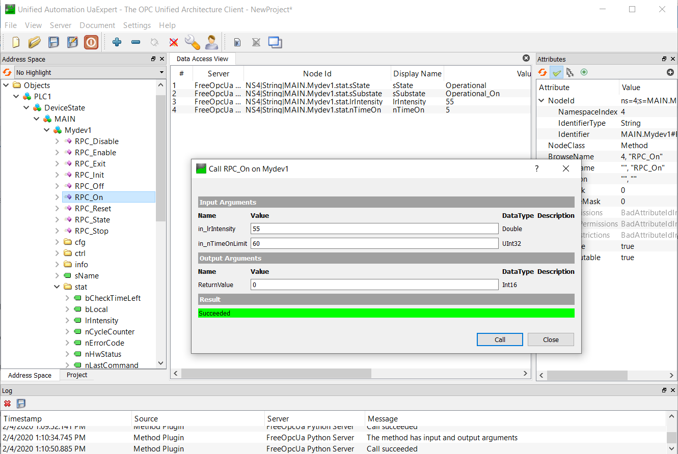
Namespace of generated Device Simulator in UaExpert.
Note, the name “<device>1”, here “Mydev1” is merely a default name. However, often multiple instances of a device will be named e.g. “Motor1”, “Motor2”, etc. This is not a prerequisite though, and a free name may be chosen.
Adapt the Generated Code of the Device Simulator
In this section some guidelines for implementing the specific code of the new Device Simulator are provided.
Preparing the configuration:
Define the OPC UA namespace (file “namespace.yaml”, here “mydev/resource/config/mypkg/devsim/mydev/mydev.namespace.yaml”).
Define the state machine for the device (file “scxml.yaml”, here “mydev/resource/config/mypkg/devsim/mydev/mydev.scxml.xml”).
Prepare the CII Configuration Service schema file for the Device Simulator configuration (file “schema.yaml”, here “mydev/resource/config/mypkg/devsim/mydev/mydev.schema.yaml”).
Define a CII Configuration Service instance file for the Device Simulator (file “cfg.yaml”, here “mydev/resource/config/mypkg/devsim/mydev/mydev1.cfg.yaml”).
Implementing the Device Simulator business logic:
When executing Cookiecutter, the following Python source files are generated:
A source file containing constant declarations, mostly the constants defined in the PLC code (here “mydev/src/mypkg/devsim/mydev/defines.py”).
The actual Device Simulator source code (various classes implementing the logic of the simulator, here “mydev/src/mypkg/devsim/mydev/mydev.py”).
The instantiation of the Device Simulator, generating the executable (here “mydev/src/mypkgDevsimMydev.py”).
In the following the source files mentioned in the points 2. and 3. above are described in more details.
Device Simulator Class File (here “mydev/src/mypkg/devsim/mydev/mydev.py”):
The Device Simulator Class file contains the following main parts:
The classes implementing the Activities of the State Machine Chart. These are running in threads in the simulator. Example “Class ActivityInitialising()”.
The Action Manager Class (“class ActionMgr”), which defines the actions implemented by the Device Simulator and creates and registers the Activity Classes in the SCXML Engine.
The Device Simulator Class implementing the logic of the simulator. In the example above “class DevsimMydev()”. This shall be derived from the base class “devsimBase.DeviceSimulatorBase”. The Device Simulator Class provides the following methods to initialise the simulator and implementing the behaviour:
3.1. The constructor defining basic properties of the simulator, defining a mapping between the textual and numerical representation of the states defined and defining/instantiating/initialising other members of the simulator class.
3.2. An “initialise()” method which starts the Simulation Thread (see below) and sets initial valus for various parameters in the OPC UA namespace, either from the configuration or constant values.
3.3. The Simulation Thread (“sim_thr_user()”), which can be used to implement dynamic behaviour of the simulator, e.g. for a tracking device, simulating that it is tracking.
3.4. A callback function, which is invoked when changes are introduced in the OCP UA namespace in the simulator (“data_change_handler()”).
3.5. The methods implementing the RPC calls of the OPC UA interface.
In order to read and write from/to the internal OPC UA namespace, the methods “<simulator class>.read_node()” and “<simulator class>.write_node()” can be used.
Device Simulator Instantiation (here “mydev/src/mypkgDevsimMydev.py”):
The Device Simulator Instantiation source file contains the main function to start up and execute the simulator server process.
In the template an option is provided to implement specific behaviour at instatiation level. If not used, the class definition contained in the instantiation source file, may be omitted.