Engineering Interfaces
Device Manager GUI
The Device Manager provides an engineering interface that enables an easy control and monitor of the devices managed by the server. Each device type has a dedicated widget and the list of widgets is built reading the configuration at startup. Devices can be controlled individually using the Setup button within each device widget or collectively using the Setup button at the top right of the GUI.
$ fcfGui -h
Usage: fcfGui [options]
Description: This is the generic FCF GUI

Options:
-h, --help                                                 Displays help on commandline options.
-u, --uri <uri>                                            Server URI
-l, --loglevel <ERROR|INFO|DEBUG|TRACE>                    Specify Loglevel
-s, --stylesheet-name <Default||Combinear|Diffnes|Takezo>  Specify built-in stylesheet
-f, --stylesheet-file <stylesheet>                         Specify stylesheet file
-p, --pollinterval <500>                                   Specify DB polling interval (default 500ms)
Warning
The GUI gets the configuration directly from the server at start-up. If the server is not running, the GUI will be blocked until getting a timeout.
An example how to start the fcfgui from the command line is shown
below.
$ fcfGui --uri `geturi fcs-req`
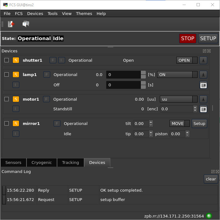
Device Manager Engineering Graphical Interface.
Stylesheets
The GUI in version 4 has been modified to remove most of the hardcoded styles. The look&feel of the GUI can now be defined externally through QT stylesheets. The FCF GUI provides a predefined set of styles that the user could select at the startup through the command option -s. These stylesheets are coming from the site qss-stock (Style Sheets) but they have been slightly modified to include some ESO specifics settings.
The users can also provide their own QSS files by using the option -f.
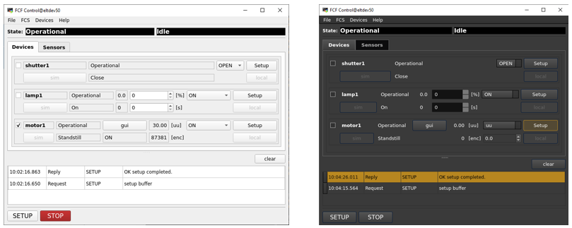
FCS main GUI started with two different styles.
Dock Widgets
The FCF GUI in version 4 has been updated to use of Qt dock widgets. The dock widgets allow the user to arrange the design of the GUI at runtime. Docks widgets can be moved, resized and stacked or even moved outside the main window.
Device Widgets
Device widgets share some common features.
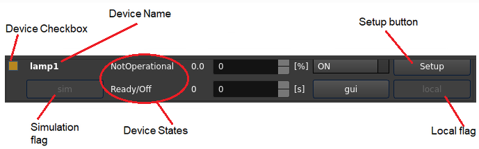
Common Widget Elements.
Note
The menu FCS enables to control the main states of the server. The server can be also restarted from this menu.
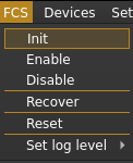
FCF menu.
Note
The menu Devices enables to control directly one or more device controllers running in the PLC. Devices can be either ignored or simulated as well from this menu.
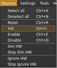
Devices menu.
At the bottom, a command window is included reporting the commands sent and the replies received by the GUI.
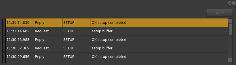
Command window widget.
The GUI does not prevent the execution of parallel Setup commands. This is achieved by creating a new thread per each command.
Selection Check-box
This checkbox shall be used to select/unselect a device. The global Setup button at the bottom is
applied only to the selected devices. In the same way, actions in the Devices menu are also
affecting the selected devices.
Device Name
Here is displayed the name of the device taken from the FCF configuration.
Simulation Flag
This flag indicates when the device is set into simulated. This means that Device Manager will use the simulation address to connect to the device controller.
Error Flag
This flag indicates when the device has got an error. The associated error message is shown as part of the button tooltip information.
Local Flag
This flag indicates when the device is set into local mode. Setup actions are rejected by the controllers when they are in local mode.
Device States
These two fields present the state and substate of the controller in the PLC. This information is read by the Device Manager. When Device Manager is not in Ready or Operational state, these values are undefined.
Setup Button
Each device with the exception of sensors can be setup individually from each widget.
Activity Feedback
This is a coloured and spinning feedback allowing the user to have a quick overview of any ongoing activity in the controller associated to the device, for instance if a derotator is tracking, the activity feedback will show it in magenta. This is faster to understand than reading each individual substate. This might be useful during initialisation phase.

Device activity feedback.
Motor Widget
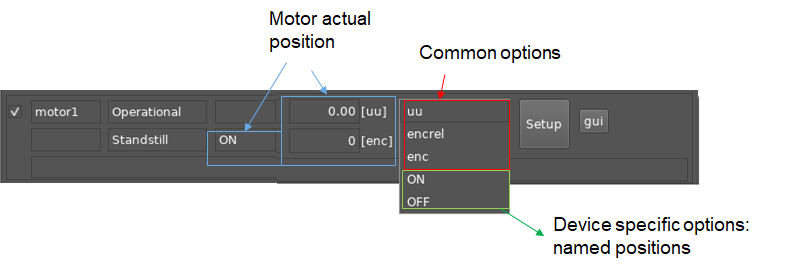
Motor Widget.
The motor widget allows moving a motor in:
Absolute user units (uu) and encoders (enc)
Relative encoders (encrel)
By name positions
Options 1 and 2 are common for all motor widgets while named position (3) may change per motor device. The named positions are read by the widget from the FCF configuration at the startup. The mapping between named positions and user units is done by the Device Manager.
Drot Widget
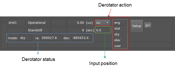
Drot Widget.
The drot widget allows selecting the operation mode and the position angle. There are three tracking modes supported by a drot device: Sky, Elevation (Elev) and User Specific (User). Additionally, a drot device can be controlled as a normal motor by selecting the Engineering mode (eng), this means moving it by user units or encoders.
Adc Widget
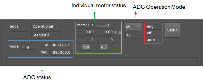
ADC Widget.
The ADC widget allows to control the operation mode of an ADC device. There are two defined modes supported by an ADC: Stationary (off) and Automatic (auto). Additionally, an ADC device can control each individual motor by selecting the Engineering mode (eng). The ADC status reports the actual run-time configuration of the device.
Motor Engineering GUI (fcfMotGui)
The Motor device provides an additional engineering interface offering
more details for the control and monitoring of motorized devices
(fcfMotGui). With this GUI it is possible to see the motor position
or the activation of signals during initialisation. The motor can be
controlled in Position or in Velocity mode.
The fcfMotGui can be launched directly from the command line or
from each Motor widget by pressing the  button.
$ fcfMotGui --help
usage: fcfMotGui [-h] -d DEVICE -a ADDRESS -p PREFIX [-n NS]
            [-l {INFO,DEBUG,ERROR}] [-s STYLERESOURCE] [-f STYLEFILE]

optional arguments:
-h, --help            show this help message and exit
-d DEVICE, --device DEVICE
                    Set motor device.
-a ADDRESS, --address ADDRESS
                    Set PLC address, e.g. opc.tcp://134.171.59.98:4840
-p PREFIX, --prefix PREFIX
                    Set motor prefix, e.g. MAIN.Motor1
-n NS, --ns NS        Set OPCUA namespace, e.g. 4
- l {INFO,DEBUG,ERROR}, --loglevel {INFO,DEBUG,ERROR}
                    set the logging level: INFO|DEBUG|ERROR
-s STYLERESOURCE, --styleresource STYLERESOURCE
                    Set stylesheet resource, e.g. mystyle.qss
-f STYLEFILE, --stylefile STYLEFILE
                    Set stylesheet file, e.g. mystyle.qss
An example how to start the fcfMotGui from the command line is
shown below.
$ fcfMotGui -d motor1 -a opc.tcp://127.0.0.1:7578 -p MAIN.Motor1 -s Combinear.qss
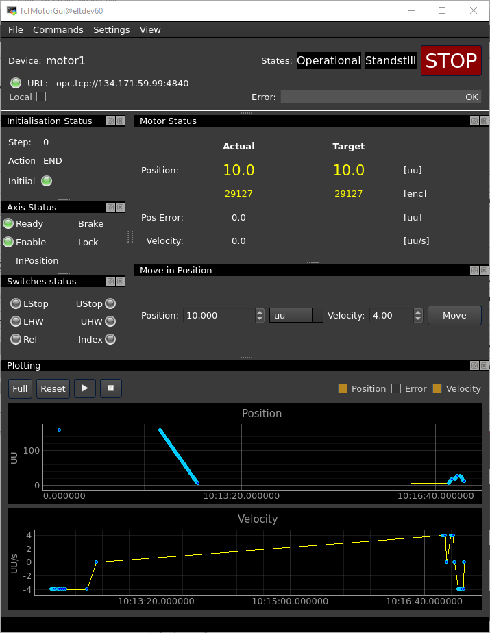
Motor Graphical Interface.
Initialisation Markers
The Motor GUI uses markers to identify the time when motors reach a switch during the initialisation sequence. Two markers indicate the start and the end of the sequence, the others will depend of the switches reached during the sequence, see an example in the image below. In this example it was marked lower and higher hardware limits.
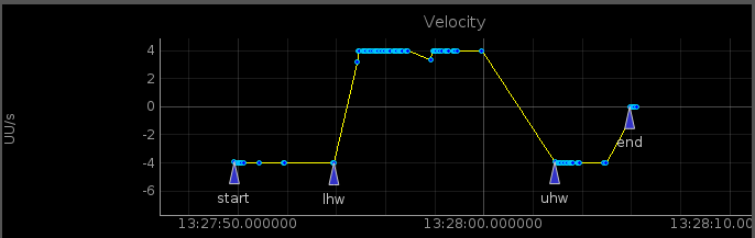
Example of Initialisation Markers.
Exporting Plotting Data
The plotting data can be exported in a PNG or JPG format. This can be achieved by doing the following steps:
Press mouse right-button and select “Export…”
Select “Image File (PNG,TIF, JPG,..” from Export format and press “Export”, see image below.
Define the name of the file, e.g. myplotdata.png and press “Save”.
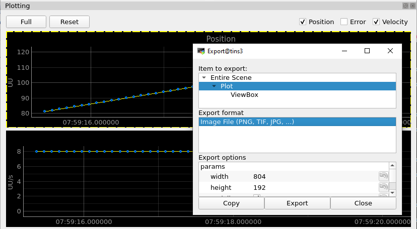
Exporting Plotting Data.
Note
You can use the same procedure for exporting the data into an ASCII file by selecting the proper option for the export format (CSV).
Lamp Engineering GUI
The Lamp device provides an additional engineering interface offering
more details for the control and monitoring of lamp devices
(fcfLampGui). With this GUI it is possible to see details of the
lamp timers or the value of the analog feedback.
The fcfLampGui can be launched directly from the command line or
from each Lamp widget by pressing the gui button.
$ fcfLampGui --help
usage: fcfLampGui [-h] -d DEVICE -a ADDRESS -p PREFIX [-n NS]
             [-l {INFO,DEBUG,ERROR}] [-s STYLERESOURCE] [-f STYLEFILE]

optional arguments:
 -h, --help            show this help message and exit
-d DEVICE, --device DEVICE
                    Set lamp device.
-a ADDRESS, --address ADDRESS
                    Set PLC address, e.g. opc.tcp://134.171.59.98:4840
-p PREFIX, --prefix PREFIX
                    Set motor prefix, e.g. MAIN.Motor1
-n NS, --ns NS        Set OPCUA namespace, e.g. 4
-l {INFO,DEBUG,ERROR}, --loglevel {INFO,DEBUG,ERROR}
                    set the logging level: INFO|DEBUG|ERROR
-s STYLERESOURCE, --styleresource STYLERESOURCE
                    Set stylesheet resource, e.g. mystyle.qss
-f STYLEFILE, --stylefile STYLEFILE
                    Set stylesheet file, e.g. mystyle.qss
An example how to start the fcfLampGui from the command line is
shown below.
$ fcfLampGui -d lamp1 -a opc.tcp://127.0.0.1:7578 -p MAIN.Lamp1 -s Combinear.qss
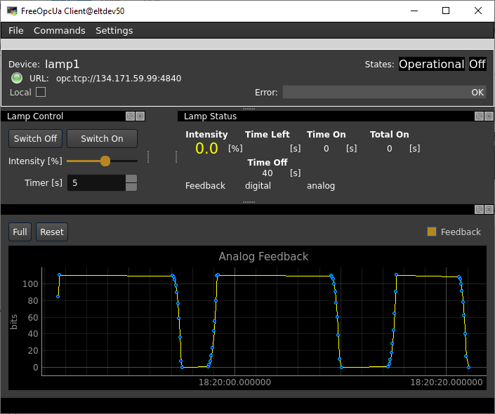
Lamp Graphical Interface.