2 OVERVIEW
2.1 INTRODUCTION
ICS, according to the definitions given in [6], is the only software responsible for controlling the instrument hardware (excluded the detectors). When other software (e.g. OS or MS) wants to access
this HW, it has to go through ICS.In this chapter a brief description of the internal architecture of the ICS package for a generic instrument is given. The rest of the manual is organized in the following chapters:
· Chapter 3 introduces ICS to beginners by mean of a demo session on the Template Instrument, that is delivered with the package.
· Chapter 5 is a tutorial that describes step by step how to implement an instrument specific ICS from scratch.
· Chapter 6 is a tutorial that describes how to implement a special ICS software device, specific to an instrument.
· Chapter 7 complements the user's guide providing additional information to software developers who have to modify or improve an existing ICS based on the icb package.
· Chapter 8 is the configuration guide that describes in detail how to configure ICS. The chapter lists the supported ICS software device types and the way how each of them is configured.
· Chapter 10 is an installation guide that describes how to install an ICS based on the icb package.
Other information about ICS can be found in related documents, as described in sections 1.2 and 3.1.
2.2 NAMING CONVENTIONS
<xx> is a two characters prefix indicating the instrument (e.g. tc for Test Camera, is for ISAAC, uv for UVES)
<Functionality> is a string indicating what the process/script is supposed to do, in conformity with what specified in [5].
2.3 ARCHITECTURE
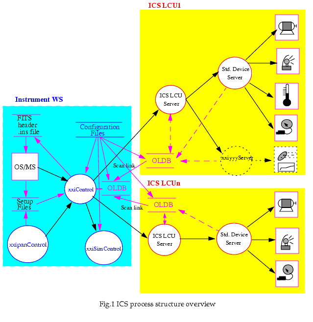
ICS controls the different devices of the instrument such as motors, shutters, lamps and sensors. These devices, also referred to as instrument functions, are driven by standard ESO hardware such as motor controllers and digital I/O boards connected to an LCU. In order to control the hardware a corresponding software device is needed. The ICS LCU consists of a set of ICS software devices managed by device servers.
The ICS SW is split into a WS and an LCU part. Fig.1 shows its general architecture.

2.3.1 Workstation
The Workstation part consists of:
1. One main process (xxiControl), which acts as front-end for all incoming commands, both from higher level sw modules (OS or MS), or directly from the ICS stand-alone GUI panel (xxipanControl). The main responsibilities of this process are:
2. One auxiliary process (xxiSimControl), used only when the ICS sw runs in simulation mode. It simulates the behaviour of the LCUs (hardware and software). When the ICS LCU sw is simulated, all commands normally sent to the LCUs are routed by the WS ICS front-end process to the ICS Simulation process.
3. GUI panel (xxipanControl) to be able to interact with UVES ICS as stand-alone sw module and allow therefore engineers to test the behaviour of the instrument.
Processes 1. and 2. are based on the VLT Event Handling Toolkit (see [18]).
Process 3. is based on the VLT panel editor (see [20]).
2.3.2 LCU
1. One main process (ICS LCU server), which acts as front-end for all commands coming from the WS. If a command is intended to be executed by several software devices, then the ICS LCU server sends one command to each individual software device. This approach corresponds to what prescribed by the VLT applications guidelines document (see [5]) for LCU application software.
2. Standard software devices are managed by a device manager (Std. Device Server). This server deals with all requests for the standard devices. The server receives one command for each individual software device, this allows to spawn one task for each software device and to execute the command in parallel. The devices are:
3. Special software devices (xxiyyyServer), for functions needing a special treatment. They are developed and maintained by the instrument team.
icb defines only the rules and the interface; additionally it provides templates to simplify the development of special devices control sw.
The values of the LCU OLDB attributes used by GUI panels on the WS for status display are updated regularly in the WS database via the CCS scan system.
As a general rule, the scan system should be used exclusively for status display through WS panels. ICS sw should not rely for control purposes on OLDB values scanned from LCU to WS; the scan system works asynchronously with respect to the ICS message flow and time synchronization is a critical issue, which should be avoided.
2.4 SOFTWARE MODULES
The generic ICS software is accessed via the icb software module.
Instrument specific modules should be listed in the instrument specific ICS User Manual (see [23] for an example).
|
Quadralay Corporation http://www.webworks.com Voice: (512) 719-3399 Fax: (512) 719-3606 sales@webworks.com |