1 INTRODUCTION
The software described in this manual is intended to be used in the ESO VLT project by ESO and authorized external contractors only.
While every precaution has been taken in the development of the software and in the preparation of this documentation, ESO assumes no responsibility for errors or omissions, or for damage resulting from the use of the software or of the information contained herein.
1.1 PURPOSE
The purpose of this document is to describe the usage of the Base ICS software package: the manual describes the features supplied by Base ICS and how an ICS implemented with Base ICS is used. The tutorials describe how the Base ICS and its related Template Instrument software modules are used and configured to implement a specific ICS.
Starting from issue 2.0 it describes the usage of a reviewed version of this package, called also icb.
Previous issues (1.x) described the usage of the prototype version of the package, called also ic0; the public interface of that version has to be considered obsolete.
1.2 SCOPE
This document is intended for software developers of instrumentation software for the VLT project.
The related Template Instrument manual [23] describes a template instrument (modules xxins, xxi, etc.) that can be used as a template to build a specific real instrument.
This document does not enter into internal implementation details of the icb package; this will be found in the Maintenance Manual.
1.3 APPLICABLE DOCUMENTS
The following documents, of the exact issue shown, form a part of this document to the extent specified herein. In the event of conflict between the documents referenced herein and the contents of this document, the contents of this document shall be considered as a superseding requirement.
[1] GEN-SPE-ESO-19400-0794, 2.0 31/10/97 --- DICB - Data Interface Control Document
[2] VLT-SPE-ESO-10000-0011, 2.0 30/09/92 --- VLT Software Requirements Specification
[3] VLT-PRO-ESO-10000-0228, 1.0 10/03/93 --- VLT Software Programming Standards
[4] VLT-PLA-ESO-10000-0441, 1.0 01/05/95 --- VLT Science Operation Plan
[5] VLT-MAN-ESO-17210-0667, 1.0 03/12/97 --- Guidelines for VLT applications.
[6] VLT-SPE-ESO-17212-0001, 2.0 23/02/95 --- INS Software Specification
[7] VLT-SPE-ESO-17240-0385, 2.1 15/07/96 --- INS Common Software Specification
[8] VLT-ICD-ESO-17240-19400, 2.6 17/11/97 ---- ICD between VCS and Archive
[9] VLT-ICD-ESO-17240-19200, 1.0 29/10/96 ---- ICD between VCS and OH
1.4 REFERENCE DOCUMENTS
The following documents are referenced in this document.
[10] VLT-MAN-ESO-17200-0888, 1.0 17/08/95 ---- VLT Common Software Overview
[11] VLT-MAN-ESO-17200-0642, 1.11 22/11/99 ---- VLT Common Software Installation Manual
[12] VLT-SPE-ESO-17120-1355, 1.2 12/01/99 --- Final Lay-out of VLT Control LANs
[13] VLT-MAN-SBI-17210-0001, 3.4 05/05/97 --- LCU Common Software User Manual
[14] VLT-MAN-ESO-17210-0600, 1.6 17/11/97 --- Motor Control sw User Manual API/ACI
[15] VLT-MAN-ESO-17210-0669, 1.4 20/10/97 --- Motor Engineering Interface User Manual
[16] VLT-MAN-ESO-17210-0619, 1.5 31/05/96 --- Central Control Software User Manual
[17] VLT-MAN-ESO-17210-0707, 1.5 30/04/97 --- On Line Database Loader User Manual
[18] VLT-MAN-ESO-17210-0771, 1.5 30/11/97 --- EVH User Manual
[19] VLT-MAN-ESO-17210-0770, 1.5 30/11/97 --- Extended CCS User Manual
[20] VLT-MAN-ESO-17210-0690, 3.2 26/11/97 --- Panel Editor User Manual
[21] VLT-MAN-ESO-17240-0853, 1.3 03/11/97 --- INS Common sw - oslx User Manual
[22] VLT-MAN-ESO-17240-2325, 1.1 08/04/01 --- INS Common sw - Config Tool User Manual
[23] VLT-MAN-ESO-17240-1973, 2.0 08/04/01 --- Template Instr. Software User Manual
[24] VLT-PLA-ESO-17240-2266, 1.0 17/08/00 --- Acceptance Test Plan Template Document
[25] VLT-MAN-ESO-17220-0737, 2.0 07/11/97 --- HOS - Sequencer User Manual
[26] P.Ward, S.Mellor, Yourdon Press, 1985 --- Struct. Development for Real-Time Systems
[27] J. Rumbaugh et. al., Prentice Hall, 1991 --- Object-Oriented Modelling and Design
1.5 ABBREVIATIONS AND ACRONYMS
The following abbreviations and acronyms are used in this document:
ACC Access and Configuration Control
CCS Central Control Software
CPU Central Processing Unit
DCS Detector Control Software
ESO European Southern Observatory
FITS Flexible Image Transport Format
GUI Graphical User Interface
ICS Instrument Control Software
INS Instrumentation Software Package
ISAAC Infrared Spectrograph and Array Camera
IWS Instrument Workstation
OMT Object Modelling Technique
OOD Object Oriented Design
OSS Observer Support Software
TCS Telescope Control Software
TIM Time Interface Module
TRS Time Reference System
UIF (Portable) User Interface (Toolkit)
UVES UltraViolet Visual Echelle Spectrograph
VME Versa Module Eurocard
1.6 GLOSSARY
No special definition is introduced in this manual
1.7 STYLISTIC CONVENTIONS
The following styles are used:
bold in the text, for commands, filenames, pre/suffixes as they have to be typed.
italic in the text, for parts that have to be substituted with the real content before typing.
<name>
in the examples, for parts that have to be substituted with the real content before typing.
bold and italic are also used to highlight words.
1.7.1 Data Flow and Processor Model Diagrams
Data Flow and processor Model Diagrams are based on De Marco/Yourdon notation for real-time systems [26].
1.7.2 Class Diagrams
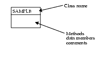
Class diagrams are based on OMT notation [27]
In order to simplify drawing of class symbols, a class is represented by a box, divided in two sections:
Lines connecting classes have to be interpreted as follows:
Class hierarchies are also represented as tree diagrams with the base class on the left and derived classes on the right, connected by lines:
1.8 NAMING CONVENTIONS
This implementation follows the naming conventions as outlined in [3].
1.9 PROBLEM REPORTING/CHANGE REQUEST
The form described in [11] shall be used.


