Getting Started
Log-in
Login to a standard ELT machine.
Retrieve and build the Software
If not yet done, retrieve the complete ICS Framework from the ESO Gitlab site. Integration area shall be defined in advance. With the upgrade to GIT repository, the IFW has been divided in several WAF projects. Each one shall be retrieved, built and installed. For more details, please have a look to the installation procedure here
cd ifw-hl/fcf; waf configure; waf install
Starting Database Server
The present version of the Device Manager uses Redis as the database engine to store run-time configuration (Redis documentation).
Before running the Device Manager is required to start up the DB
server executing the following command:
redis-server &
Note
When no port is specified, the Redis DB server uses the port 6379.
The data is stored in the DB using a list of keyword/values. Each keyword has a hierarchical name that helps to idenfify its context, for instance the keys associated to a Device Manager start with the <server id> defined in the FCF configuration.
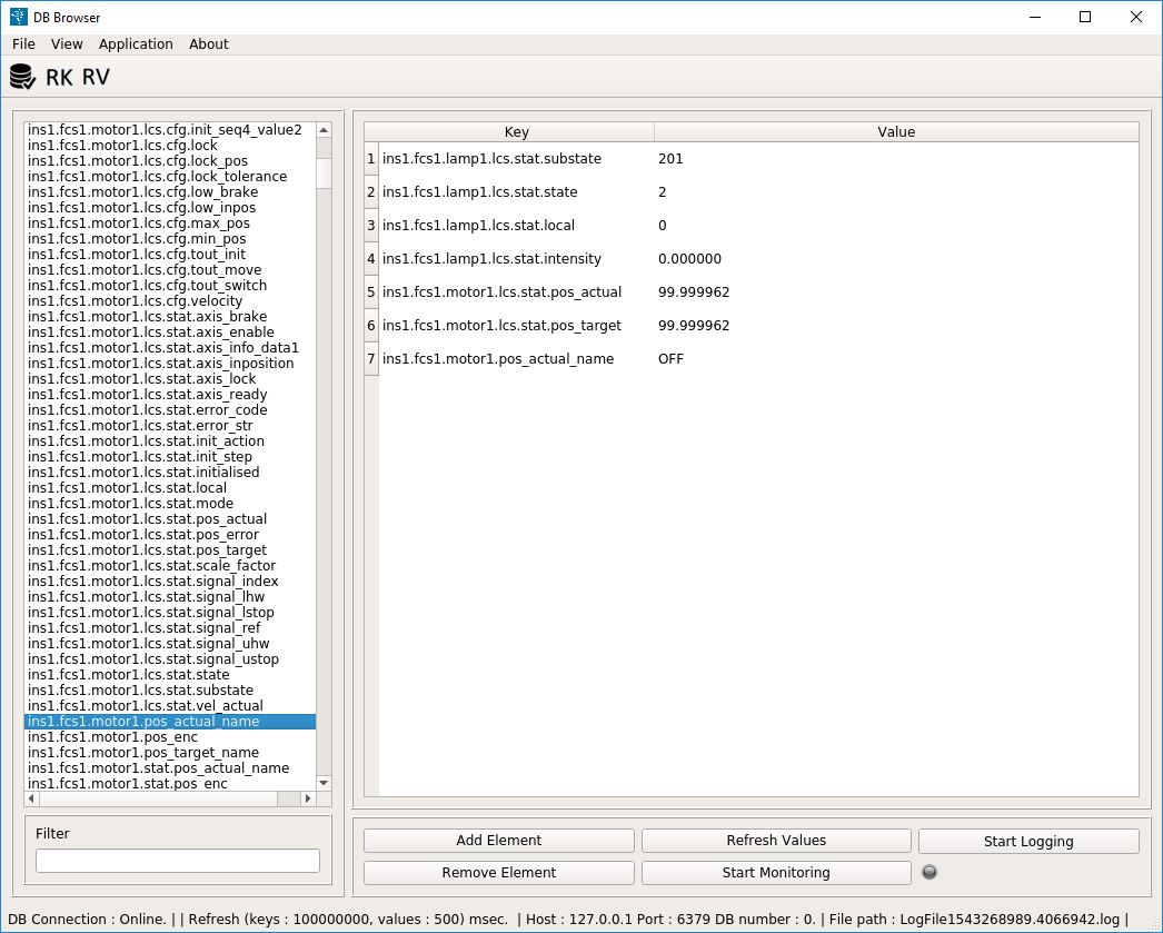
The ELT development environment provides a DB browser tool (dbbroser) that can be used to monitor the database keywords in an easy way similar to the ccseiDb tool in the VLT project.

Dbbrowser tool screenshot showing Device Manager attributes.
dbbrowser &
Note
To get list of attributes in the dbbrowser is needed to configure the connection first. Menu Application option Open. Consult the dbbrowser User Manual in case of problems.
Note
The attributes will be populated only when the Device Manager server is started.
Creating a FCS Configuration
The FCF includes a templates that can be used to generate the configuration files for an instrument FCS. The generated directory contains a fully working waf project with a custom FCS including a special device. In this example we will use “tins” as an example instrument. After executing the cookiecutter command with the provided template, the system will request the user input to enter the information for the generation of the configuration and customized code. This template also generates the code for a special device that in this case we will name as “mirror”.
cookiecutter ifw-hl/fcf/templates/project
project_name [myproject]: tins
project_description [this is my project description]:
component_name [mycomponent]: fcs1
interface_name [myif]: myif
device_name [mydevice]: mirror
After the new directory is created, one could build and install the generated software.
cd tins
waf configure
waf build install
The Device Server requires a configuration file including all the
relevant information for the server. A pre-defined configuration has been created as part of the generation
process. This configuration include three devices.
Generated server configuration: fcs1/server/cfg_sim.yml
server_id           : 'tins.fcs1.std'

tins.fcs1.std:
    req_endpoint    : "zpb.rr://127.0.0.1:12081/"
    pub_endpoint    : "zpb.ps://127.0.0.1:12345/test"
    db_endpoint     : "127.0.0.1:6379"
    db_timeout      : 2
    scxml           : "fcf/devmgr/server/sm.xml"
    dictionaries    : ['dit/stddid/primary.did', 'fcf/devmgr/server/fcf.did']
    fits_prefix     : "FCS1"

    devices         : ['shutter1', 'lamp1', 'motor1']
    cmdtout         : 60000

shutter1:
    type: Shutter
    cfgfile: "fcs1/server/shutter1_sim.yml"

lamp1:
    type: Lamp
    cfgfile: "fcs1/server/lamp1_sim.yml"

motor1:
    type: Motor
    cfgfile: "fcs1/server/motor1_sim.yml"
Note
This configuration shall be adapted to the instrument specific needs.
The generated configuration also includes, the specific configuration for a custom server: fcs1/server/custom_sim.yml
This server is aimed to manage a custom device (Mirror).
server_id           : 'tins.fcs1.custom'

tins.fcs1.custom:
    req_endpoint    : "zpb.rr://127.0.0.1:12081/"
    pub_endpoint    : "zpb.ps://127.0.0.1:12345/test"
    db_endpoint     : "127.0.0.1:6379"
    db_timeout      : 2
    scxml           : "fcf/devmgr/server/sm.xml"
    dictionaries    : ['dit/stddid/primary.did', 'fcf/devmgr/server/fcf.did']
    fits_prefix     : "FCS1"

    devices         : ['mirror1']
    cmdtout         : 60000


mirror1:
    type: Mirror
    cfgfile: "fcs1/server/mirror1.yml"
Warning
The custom server cannot combine standard devices with custom ones. This implies you need always a dedicated server for instrument specific devices.
Starting Device Manager
$ fcfDevmgr -c fcs1/server/cfg_sim.yml -l INFO
The output of the server shall be something like the following:
2020-05-05T21:36:29.450933   INFO Application fcfDevmgr started.
2020-05-05T21:36:29.453517   INFO CfgFile - req_endpoint = <zpb.rr://127.0.0.1:12083/>
2020-05-05T21:36:29.453547   INFO CfgFile - db_endpoint = <127.0.0.1:6379>
2020-05-05T21:36:29.453563   INFO CfgFile - pub_endpoint = <zpb.ps://127.0.0.1:12347/test>
2020-05-05T21:36:29.453713   INFO CfgFile - Devices: 3
2020-05-05T21:36:29.453735   INFO shutter1
2020-05-05T21:36:29.453789   INFO lamp1
2020-05-05T21:36:29.453814   INFO motor1
2020-05-05T21:36:29.508383   INFO [shutter1] Warning device simulated !
2020-05-05T21:36:29.508658   INFO [shutter1] reading configuration keywords ...
2020-05-05T21:36:29.510760   INFO [shutter1] Publishing Endpoint: zpb.ps://127.0.0.1:12345/testshutter1
2020-05-05T21:36:29.616945   INFO [lamp1] Warning device simulated !
2020-05-05T21:36:29.617129   INFO [lamp1] reading configuration keywords ...
2020-05-05T21:36:29.621031   INFO [lamp1] Publishing Endpoint: zpb.ps://127.0.0.1:12345/testlamp1
2020-05-05T21:36:29.728769   INFO [motor1] Warning device simulated !
2020-05-05T21:36:29.730324   INFO [motor1] reading init sequence ...
2020-05-05T21:36:29.730395   INFO [motor1] number of init actions: 4
2020-05-05T21:36:29.730894   INFO [motor1] reading name position:motor1
2020-05-05T21:36:29.730957   INFO [motor1] number of named positions: 2
2020-05-05T21:36:29.731257   INFO [motor1] reading named position tolerance:motor1
2020-05-05T21:36:29.731337   INFO [motor1] named position tolerance: 1
2020-05-05T21:36:29.735476   INFO [motor1] Publishing Endpoint: zpb.ps://127.0.0.1:12345/testmotor1
2020-05-05T21:36:29.739185   INFO [motor1] Publishing Motor Endpoint: zpb.ps://127.0.0.1:12345/testmotor1/position
INFO - ZpbServer: Server bound to 'tcp://127.0.0.1:12081
INFO - ZpbServer: Creating server reply listener socket and binding to inproc://zpbServer.0
INFO - ZpbServer: Creating server reply notifier socket and connecting to inproc://zpbServer.0
INFO - ZpbServer: Registering service 'StdCmds' with hash 1187070201.
INFO - ZpbServer: Registering service 'CustomCmds' with hash 1764819398.
Note
The server can be started with option -l ERROR to remove the information logs.
Initialising the server
The client application can be used to send commands to the server from the command line:
$ fcfClient zpb.rr://127.0.0.1:12083/StdCmds fcfif.Init ""
The reply from the server shall be something like the following:
[shutter1] Connection failed :Error obtaining endpoints for address: opc.tcp://127.0.0.1:7576
Starting the Simulators
To avoid the above problem, the simulators shall be started. Each simulator is attempting to mimic the interface and behaviour of the corresponding device controller. Each simulator contains an OPC-UA server listening in the specified port. The address space of the OPC-UA server matches the one from the real device.
fcfDevsimLamp --port 7577 --cfg fcs1/devsim/lamp1_devsim.yml
fcfDevsimShutter --port 7576 --cfg fcs1/devsim/shutter1_devsim.yml
fcfDevsimMotor --port 7578 --cfg fcs1/devsim/motor1_devsim.yml
Note
The port number have to match the configuration endpoint in each device configuration.
Now that the simulators are running, the server can be initialised.
$ fcfClient zpb.rr://127.0.0.1:12083/StdCmds fcfif.Init ""
If the initialisation is succesfull, the server will go to NotOperational/Ready. Now it is possible to move it to Operational by sending the command Enable.
$ fcfClient zpb.rr://127.0.0.1:12083/StdCmds fcfif.Enable ""
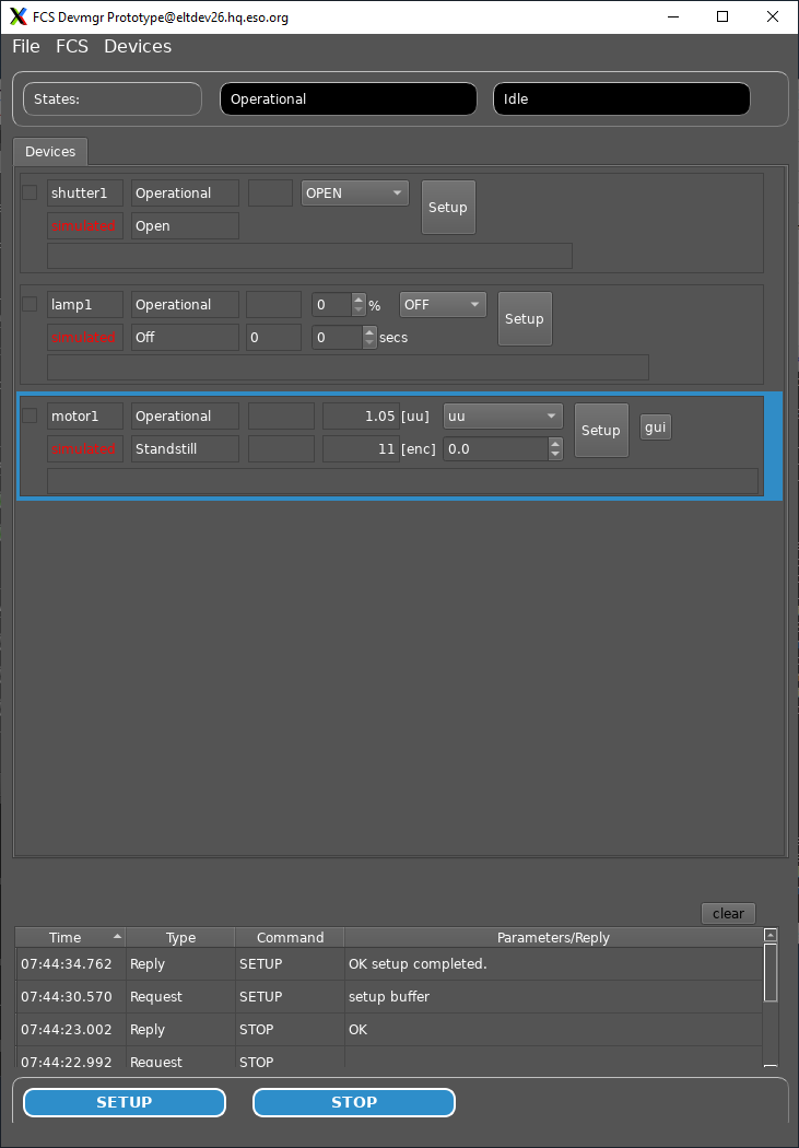
In Operational state, the server accepts the Setup command to control the devices, for instance the status of the Shutter (open or close). You can try setting up the Shutter with the Device Manager GUI.
Using the DeviceManager GUI
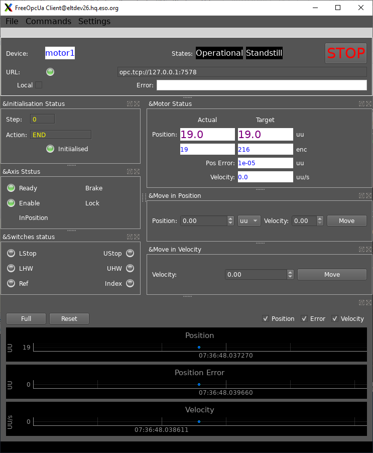
Using the Motor Engineering GUI
Starting Custom Device Manager
This server controls a custom device that might be needed for instrument specific requirements.
$ fcs1DevMgr -c fcs1/server/custom_sim.yml -l INFO
Note
This is a custom Device Manager and not the generic one included in the FCF component.
The output of the server shall be something like the following:
2020-05-06T08:04:47.146900   INFO Application fcs1Devmgr started.
2020-05-06T08:04:47.148970   INFO CfgFile - req_endpoint = <zpb.rr://127.0.0.1:12081/>
2020-05-06T08:04:47.148999   INFO CfgFile - db_endpoint = <127.0.0.1:6379>
2020-05-06T08:04:47.149015   INFO CfgFile - pub_endpoint = <zpb.ps://127.0.0.1:12345/test>
2020-05-06T08:04:47.149145   INFO CfgFile - Devices: 1
2020-05-06T08:04:47.149165   INFO mirror1
2020-05-06T08:04:47.203342   INFO [mirror1] Warning device simulated !
2020-05-06T08:04:47.203427   INFO [mirror1] reading configuration keywords ...
2020-05-06T08:04:47.207806   INFO [mirror1] Publishing Endpoint: zpb.ps://127.0.0.1:12345/testmirror1
INFO - ZpbServer: Server bound to 'tcp://127.0.0.1:12081
INFO - ZpbServer: Creating server reply listener socket and binding to inproc://zpbServer.0
INFO - ZpbServer: Creating server reply notifier socket and connecting to inproc://zpbServer.0
INFO - ZpbServer: Registering service 'StdCmds' with hash 1187070201.
INFO - ZpbServer: Registering service 'CustomCmds' with hash 1764819398.
Note
The server can be started with option -l ERROR to remove the information logs.
Initialising the Custom Server
The client application can be used to send commands to the server from the command line:
$ fcs1Client zpb.rr://127.0.0.1:12081 fcfif.Init ""
Note
This is a custom Client and not the generic one included in the FCF component.
The reply from the server shall be something like the following:
[mirror1] Connection failed :Error obtaining endpoints for address: opc.tcp://127.0.0.1:7777
Starting the Custom Simulator
To avoid the above problem, the simulator shall be started.
fcs1Devsim_mirror --port 7777 --cfg fcs1/devsim/mirror/mirror1.yaml
Note
The port number have to match the configuration endpoint in each device configuration.
Note
The mirror device has its custom simulator (fcs1Devsim_mirror).
Now that the simulator is running, the server can be initialised.
$ fcs1Client zpb.rr://127.0.0.1:12081 fcfif.Init ""
If the initialisation is succesfull, the server will go to NotOperational/Ready. Now it is possible to move it to Operational by sending the command Enable.
$ fcs1Client zpb.rr://127.0.0.1:12081 fcfif.Enable ""
In Operational, the server accepts the Setup command to control the status of the Mirror.
Warning
The mirror device is a dummy device that is a showcase how to develop custom devices.
The mirror device includes a setup that triggers the execution of a custom RPC in the controller (simulator).
$ fcs1Client zpb.rr://127.0.0.1:12081 myif.Setup ""
The reply from the server shall be something like the following:
2020-05-06T08:39:16.321885   INFO Started SETUP command
2020-05-06T08:39:16.322041   INFO [mirror1] Setup Action: 0
2020-05-06T08:39:16.322049   INFO Setup Notify Event !
2020-05-06T08:39:16.322065   INFO [mirror1] Executing RPC_PING ...
2020-05-06T08:39:16.323720   INFO [mirror1] Successfull call of Mirror ping:
Note
The usage of the custom interface (myif) in the command line above instead of the standard one fcfif. This is only needed for the Setup command which is the only one that is custom in the example.
Working with a PLC
The following steps can be done to use the server configuration that was generated with controllers running in a PLC.
Note
The provided PLC project includes the corresponding simulators so hardware is not needed only a bare PLC. All the mapping is pre-configured and the PLC code is generated to match the server configuration (3 devices).
Requirements
PLC available with required version of TwinCAT run-time and OPC-UA Server.
Windows development environment with required TwinCAT software installed.
All ESO PLC libraries installed in the Windows development environment.
Load the PLC Project
From a Visual Studio load the PLC project generated. The project can be found in fcs1/LCS/plcprj1.
Select Target System
Select the target system, this is the PLC that you want to use.
Build the PLC Project
If you have errors, make sure you have all ESO libraries installed.
Activate Configuration
This active the project configuration and restart the OPC-UA Server in the PLC.
Login to the target system.
This will download the code to the PLC.
Update the configuration of each device with the corresponding PLC address (IP).
lamp1:
    type: Lamp
    interface: Softing
    identifier: PLC1                             # OPCUA Object Identifier
    prefix: MAIN.Lamp1                           # OPCUA attribute prefix
    simulated: true
    ignored: false
    address: opc.tcp://134.171.59.98:4840    # <<<---- Change the IP here
    simaddr: opc.tcp://127.0.0.1:7577        # Simulation address
    mapfile: "fcf/devmgr/server/mapLamp.yml"
    fits_prefix: "LAMP1"
    ctrl_config:
        low_fault:        false                     # If T, signal is active low
        low_on:           false                     # If T, signal is active low
        low_switch:       false                     # If T, signal is active low
        initial_state:    false
        timeout:          2000
Stop the simulation for the devices
$ fcfClient zpb.rr://127.0.0.1:12083/StdCmds fcfif.Reset ""
$ fcfClient zpb.rr://127.0.0.1:12083/StdCmds fcfif.StopSim "lamp1, shutter1, motor1"
Note
By changing the flag simulated to false in the device configuration it is possible to make this change persistent.
Set the server to operational state
$ fcfClient zpb.rr://127.0.0.1:12083/StdCmds fcfif.Init ""
$ fcfClient zpb.rr://127.0.0.1:12083/StdCmds fcfif.Enable ""
You can now operate the server with devices connected to the PLC controllers.
Stopping the Software
Stopping the GUI
The menu File has an option Exit. Please select this option if you want to stop properly the GUIs.
Stopping the Simulator processes
Please kill each process, for the moment we do not have any other mechanism to do it.
Stopping the Device Manager
Please send the command Exit to the server.
$ fcfClient zpb.rr://127.0.0.1:12083/StdCmds fcfif.Exit ""
$ fcs1Client zpb.rr://127.0.0.1:12081 fcfif.Exit ""
Stopping the Redis Db Server
Please execute the following command line.
redis-cli SHUTDOWN
Note
The above is only valid when server was started with the default port.

