6 TROUBLESHOOTING
This section provides a summary of possible failures, explanation of their probable cause and procedures to recover normal operating condition.
This section will evolve in time on the base of user experience and problems reports.
6.1 Problems during installation
This section of the troubleshooting guide copes with problems which could arise during the installation procedures.
6.1.1 How to change a Hard Disk with SCSI-3 into SCSI-0
If a Hard Disk with SCSI id 0 is not available, it is possible to modify the SCSI id of a Hard Disk with SCSI id 3 (e.g., one of the backup Hard Disks):
1. Build the SCSI chain using the SCSI-3 disk that has to become SCSI-0 and another disk which SCSI address is set to "0". This disk is used only to force the system to build the device file, the content is not touched and therefore can be any disk.
4. When the system is up, edit the /etc/vfstab replacing address 3 with 0. The line should therefore look like:
6. Switch off and remove the jumper from SCSI-3 disk to set it to SCSI-0. Remove the SCSI-0 disk used in the first part or set it to "3" by inserting the jumpers.
6.2 Problems with start-up
This section of the troubleshooting guide assumes that the installation has already been performed successfully and that the problems encountered are those of a previously running system which now fails.
6.2.1 FIERA S/W stays in OFF state
Some of the possible causes of the FIERA S/W to remain in the OFF state after the start-up script has been run are listed below:
6.2.1.1 SLCU not alive or remote SLCU environment not started
If the SLCU has failed to boot or the SLCU environment not started the FIERA S/W would remain at the OFF state and the output in the logMonitor should resemble the following:
msgSend rtWaitForAck 10 9987 1 W rtE_ENV_NOT_ACTIVE: Remote env not active REASON > No acknowledgement from env wodt2
msgSend rtWaitForAck 10 9988 1 W rtE_ENV_NOT_ACTIVE: Remote env not active REASON > No acknowledgement from env wodt2
6.2.1.2 SLCU not alive
From the INStrument workstation type the following:
The output should resemble the following:
If you do not receive any packet from the remote host this implies either
You should be able to determine if [1] is the case by trying to access other machines on the sub-net.
If you are sure the network is OK, then go to the SLCU and reset it using the reset switch on the front panel, if the SLCU continues not to boot then look at section 6.4.
6.2.1.3 SLCU environment not started
Assuming that the SLCU has booted and you are able to "ping" it, try the following from the INStrument workstation:
% msgSend $CCDLENV cmdManager PING ""
The output should resemble the following:
If instead of the above message you get an indication that the environment is not active try restarting the SLCU (see 6.4).
If the OLDB environment still does not start, log into the machine as the user fcdrun. Type the following to look for OLDB processes.
The output should resemble the following:
If the ccsScheduler is not amongst the processes listed examine the contents of the file
$VLTDATA/ENVIRONMENTS/$RTAPENV/.ccsScheduler.log
This gives the startup messages for the OLDB environment. If this file does not contain any obvious error messages, check the contents of
This contains the OLDB startup user.
6.2.1.4 Communication with DSP fails
In this situation, the FIERA S/W would stay in the OFF state. The logMonitor output would resemble the following
fcdSlcuStartupCamera:: Starting fcdc40srv_sparc_link for naos logging to /tmp/fcdc40srv_sparc_link.log.3738
If this error occurs, attempt a complete power cycle on the SLCU rack (see [6.4]). If the startup still fails then the error is with one of:
See section [6.6] for a description of standalone electronics diagnostics.
6.2.1.5 Corrupted FIERA configuration
If the FIERA configuration has been corrupted, the FIERA S/W will stay in the OFF state with the following type of output in the logMonitor.
fcdexp fcdEXP_MAIN_TASK.C:189 302 334 2 W fcdERR_GENERIC_STR : Could not Read FIERA Config from /home/fieradev/INS_ROOT_OCT98/SYSTEM/COMMON/CONFIGFILES/naos.
fcdSlcuStartupCamera ERROR:: SLCU Processes did not start up
This should only occur if someone has been modifying the readout sequence. In this case you should run the standalone configuration checking program (see section [6.5]).
6.2.2 FIERA S/W Goes to LOADED but refuses to go to STANDBY or ONLINE
Some of the possible causes of the FIERA S/W to refuse to go ONLINE are listed below:
6.2.2.1 Detector electronics switched off, or fibre disconnected
In this situation, the FIERA S/W would go to the LOADED state but would fail in the transition from LOADED to STANDBY or ONLINE. The logMonitor output would resemble the following
In this case check the fiber cables between the DSP board and the Detector Head Electronics, and ensure that the Detector Head Electronics is properly powered up. You can also run the standalone Detector Electronics Selftest S/W see section [6.6].
6.2.2.2 Detector electronics selftest failure
In this situation, the FIERA S/W would go to the LOADED state but would fail in the transition from LOADED to STANDBY or ONLINE. The logMonitor output would resemble the following
Look at the section [6.6] for instructions on running Detector Head Electronics diagnostics.
6.2.2.3 PULPO controller failure or RS232 communication failure
In this situation, the FIERA S/W would go to the LOADED state but would fail in the transition from LOADED to STANDBY or ONLINE. The logMonitor output would resemble the following
See section [6.7] for a description of PULPO troubleshooting.
6.3 Software starts but exposure status goes to FAIL
Some of the possible reasons for exposure failure are listed below:
6.3.1 Failure with the Data Capture Board
If the "readout.percent" database attribute stays at 0, then the pixels from the detector head electronics are being lost somewhere. Check the Data Capture cable between the DSP board and the SPARC, if this appears OK, then the problem lies either with the DSP board or with the Data Capture Board on the SPARC itself.
6.3.2 Failure to lock down the exposure memory
If the "readout.percent" database attribute gets to some value > 0 but less than 100, look for the following message in the logMonitor
FITS_LOG /UNFORSEEN: Readout overflow
This normally means that during the startup of the FIERA controller, the S/W was not able to "lock down" sufficient memory to ensure that the whole image fits in physical memory. In the logMonitor in the startup messages for the process fcdexp should be the message
fcdexp Failed to lock exposure into memory
The solution to this problem is to reboot the SLCU and check the startup messages to ensure that this message does not recur.
6.4 Rebooting/restarting the SLCU
Rebooting the SLCU can be done in a number of different ways depending upon how serious the failure is. The different ways are listed here in increasing order of severity.
The remote reboot techniques will only work if you are still able to log into the machine remotely, if this is not possible you will need physical access to the machine.
6.4.1 Remote reboot using OLDB environment
This is the "standard" way to restart the SLCU and can be used from INStrument S/W scripts.
From the INStrument workstation type the following
% fcdDcsSlcuReboot.sh $CCDNAME $RTAPENV $CCDLENV
This script used the restarting of the remote OLDB environment to check that the SLCU has rebooted OK.
6.4.2 Remote reboot using only operating system
This technique should be used when remote access to the machine is still possible but communication with the OLDB environment cannot be established after reboot.
From the INStrument workstation type the following
% rlogin <SLCU Hostname> -l reboot
If after some time you can "ping" the machine, you can remotely log into the machine as fcdrun and try and determine why the OLDB environment is not starting properly (see 6.2.1.3)
6.4.3 Remote halt followed by reset or power cycle
This should be used when there is a suspicion that some H/W component in the SLCU rack may be at fault, and you want to try and complete power cycle or reset or you need to power down the SLCU rack for some other reason.
From the INStrument workstation type the following.
NOTE: After performing this you MUST perform either a reset on the SLCU front panel or a complete power cycle of the SLCU rack.
6.4.4 Local halt followed by reset or power cycle
If no remote access to the machine is possible, you can connect an RS232 terminal to the front panel of the SLCU using a cable which is kept by the ODT, a dumb terminal should be connected to the cable marked "ttya". If you can get a login prompt on this terminal you can perform the following
When the OK prompt is printed it is safe to reset or cycle power on the machine.
6.4.5 Hard reset or power cycle
In the very last resort if no remote or local access to the machine is possible you can go to the machine and hit the reset button or cycle the power. This is not an operation to be undertaken lightly, there is the possibility of disk corruption leading to a completely broken system.
6.4.6 When the SLCU refuses to communicate over the network even after reboot
You can connect an RS232 terminal to the front panel of the SLCU using a cable which is kept by the ODT, the TTY should be connected to the cable marked "ttya". Then hit the reset button or cycle power.
The SLCU should output the normal boot messages indicating that it is booting from disk.
Some of the previously encountered booting problems are listed here:
6.4.6.1 Dead disk / not responding disk
If instead of booting from the disk, the SLCU prints messages like
This means that it cannot access the Disk.
If all else fails you will need to replace the disk with the spare.
6.4.6.2 Corrupted disk
You will need to run "fsck" on each of the file partitions which is corrupt, type the following:
6.4.6.3 Dead SLCU
If the SLCU does not even attempt to access the disk, then the only course of action is to replace the complete processor unit.
6.5 Running FIERA sequence checker
To check the sequences defined for a camera you need to run the following program on the SLCU, so log into the SLCU (as the user fcdrun) and type the following:
The output should resemble the following:
Checked sequence ALL_integrate_NON_MPP.
Checked sequence Tracker_test.
Checked sequence Tracker_test1.
Checked sequence Tracker_wipe.
If you get some kind of error message, this implies that the FIERA configuration is inconsistent, the error message should indicate the file name and some description of the error.
6.6 Running detector head electronics diagnostics
There is a program supplied to perform a complete Detector Head Selftest. This program needs to be run locally on the SLCU, so you will need to log into the SLCU (as the user fcdrun) and set the DISPLAY variable to the appropriate device.
You should see an Xterm appear with the title "tis", you should also see the following kinds of output.
If the Xterminal remains empty, this implies that the basic communication with the DSP is failing see [6.2.1.4].
A list of some of the more common errors which could occur during SELFTEST is included below:
6.6.1 Cabling between DSP and VME interface board is incorrect (or broken)
6.6.2 Non existent board (or board dead)
The identifier of the board is displayed.
6.6.3 Analogue bias board not reaching desired voltage
ERROR: fcdlAnb.c/535: fcdlAnbCheckVoltage: voltage of DAC 0 on ANABIAS0 should be 23.700001, but is 7.241650
ERROR: fcdlAnb.c/535: fcdlAnbCheckVoltage: voltage of DAC 1 on ANABIAS0 should be 15.300000, but is 7.241650
ERROR: fcdlAnb.c/535: fcdlAnbCheckVoltage: voltage of DAC 3 on ANABIAS0 should be 14.500000, but is 14.340405
The messages should indicate the board and DAC which are at fault.
6.6.4 SIMM on clock driver board missing or dead
If a SIMM is broken, you will get a lot of the above messages. The messages should indicate the board which is at fault.
6.6.5 Preamp disconnected or failed
The messages will indicate which video board is being tested.
6.7 PULPO trouble shooting
If there has been a problem initializing the PULPO controller or controlling the shutter, the error could be:
The steps to go through to determine the source of the problem are:
6.7.1 Check the PULPO configuration
The configuration information which affect the communication with PULPO are
6.7.1.1 pulpo.cfg
This file defines the PULPO units available and how they are attached to the SLCU
# Unit_Number Full_Device_Path
In the file above it shows that there is a PULPO Unit_Number 1 attached to physical device /dev/ttyb. If you are using one of the dedicated PULPO cables, then this is automatically "ttyb", if you are using the split cable, one of the split ends is labeled ttya, the other ttyb.
6.7.1.2 $CCDNAME.dbcfg
This is the standard CCD configuration file. One section of which defines the "type" of shutter that the camera uses. See fcdConfig in [5]. In the configuration section "Shutter" you can select PULPO2, PULPO1 or Digital.
Unfortunately, the mapping goes from PULPO2 == Unit_Number 1, PULPO1 == Unit_Number 0. So in the example here we have selected Unit_Number 1, so the fcdConfig selection should be PULPO2.
6.7.2 Check basic communication with the PULPO unit
Log into the SLCU as the user fcdrun and type the following:
This should kill any instances of the PULPO server which is running. Then restart the PULPO server and maintenance panel using the following:
On the logMonitor display, you should see the following output indicating that the initial communication with the device is complete.
If instead you see output like:
This implies either the cabling is incorrect, or the PULPO unit has stopped communicating completely.
6.7.3 PULPO control
After checking that the basic communication is OK with PULPO you can check other PULPO operations.
6.7.3.1 Basic shutter test
There is a simple test program provided to test basic shutter operation.
6.7.3.2 Comprehensive PULPO test
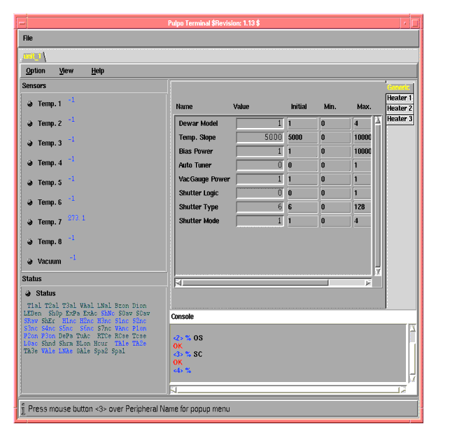
Using the PULPO maintenance panel it is possible to interact directly with the PULPO controller. Log values from temperature sensors, directly open and close the shutter etc.
6.8 Problems with Real-Time Image Display
If transfer the following error occurs at the beginning of the image:
Failed in calling CCS routine rtdInitImageEvt.
the Real Time Display is not installed or the rtdServer is not running.
Try to start rtdServer (%rtdServer &). If it fails (rtd not installed), just ignore the error: simply no image display is possible with rtd. Images can still be saved in a FITS file.
|
Quadralay Corporation http://www.webworks.com Voice: (512) 719-3399 Fax: (512) 719-3606 sales@webworks.com |