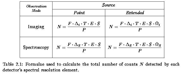
Very useful informations given by an ETC are the expected number of counts for an observed object and contribute of the sky, and the signal to noise ratio. The ETC gives also other informations which are usually instrument specific and so we prefer to describe them in other documents.
The main formulae used to evaluate the expected number of counts and the signal to noise ratio are given in the following table:

where N is the number of electrons per bin,
F is the incident flux in
![]() ,
,
![]() ,
in spectroscopy,
is the spectral bin in
,
in spectroscopy,
is the spectral bin in
![]() ,
,
![]() ,
in imaging, is the filter band width
,
in imaging, is the filter band width ![]() ,
T the total exposure time in seconds,
E the efficiency, S
the telescope surface in m2,
,
T the total exposure time in seconds,
E the efficiency, S
the telescope surface in m2,
![]() is the solid angle subtended by the integration
element (in Spectroscopy),
is the solid angle subtended by the integration
element (in Spectroscopy),
![]() is the solid angle subtended by the integration
element (in imaging),
P the energy of one photon.
The resulting dimension of N is
is the solid angle subtended by the integration
element (in imaging),
P the energy of one photon.
The resulting dimension of N is
![]() .
.
To calculate the signal to noise ratio the ETC uses the formulae:
or in the infrared:
where
is the number of spatial pixels over which it is integrated the signal
2.1,
where seeing is the seeing expressed in arcseconds;
![]() is the dimension of one pixel in arcseconds;
NObj is the total number of counts per spectral bin
coming from the
observed object (point source or extended one);
NSky is the similar term due to the sky;
RON is the contribute to the detected counts due to the Read Out Noise;
DARK is the similar term due to the dark counts.
is the dimension of one pixel in arcseconds;
NObj is the total number of counts per spectral bin
coming from the
observed object (point source or extended one);
NSky is the similar term due to the sky;
RON is the contribute to the detected counts due to the Read Out Noise;
DARK is the similar term due to the dark counts.
|
The parameters present in Table 2.1 are defined or from user specifications, the ETC front page input parameters, or by other sources of information (instrument known characteristics, physical relations, the database).
How we obtain each result is described in its own following section.