PIONIER: Detector Monitoring
| |
| HC PLOTS |
| bad pixels (full detector) |
 |
| bad pixels (science detector) |
 |
| gain (full detector) |
 |
| gain (science detetcor) |
 |
| Dark median |
 |
|
QC1 database (advanced users):
browse |
plot
|
Detector monitoring data are used to monitor the health and technical performance of the detector.
2014-12:: The detector RAPID is installed on PIONIER replacing PICNIC.
For the detector monitoring, data are recorded on the full detector. The pipeline calculates the master bad pixels maps and the gain map for the full detector and the science pixels in the different settings.
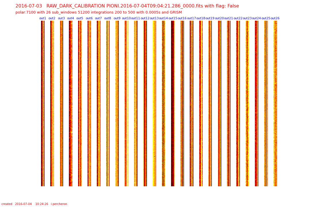
The mask for the science pixels for the GRISM contains 24 interferometric output and 2 dark output.
 |
DARK frame
|
For the science pixels : there are 2 known bad pixels and 1 non linear pixel. Their coordinates are:
[50,252] which correspond for the GRISM setting to Window 25, channel 5 (DARK)
[202,252] which correspond for the GRISM setting to Window 19, channel 1
non linear: [210,248] which correspond for the GRISM setting to Window 20 channel1
~
~
 Dark Level
The detector behaviors are characterized by measuring the dark level and the power spectral density.
Data are taken with all shutters closed. They can be taken on sky (used to calibrate sky interferometric data). or on the internal lamp (used to for the Health check plots and to monitor the instrument). Only the science channels are illuminated.
The DARK value should be stable over the scan : average all points of the scan .
QC1_parameters
| FITS key |
QC1 database: table, name |
definition |
class* |
HC_plot** |
more docu |
| QC.DARK.MED | pionier_dark..dark_med | median of DARK [adu] | HC |  | [docuSys coming] |
*Class: KPI - instrument performance; HC - instrument health; CAL - calibration quality; ENG - engineering parameter
**There might be more than one. |
Trending
The value for the dark is plotted in the trending
plot.
The Dark is plotted for the different set-up
Scoring&thresholds Dark Level
The value of the thresholds have been defined together with the Instrument scientist
History
The evolution of the dark is shown here
Algorithm Dark Level
The pipeline compute the DARK signal as an average over the scan.
TBC
 Bad Pixels
The number of bad pixels is calculated over the full detector.
Because the science data illuminate only parts of the detector, if a static mask registering the pixel illuminated is provided, the number of bad pixels are additionally derived on the detector regions not masked out by this mask.
A bad pixel on the detector which is set to unity (1) in the static mask gets excluded from the general bad pixel counts.
QC1_parameters
| FITS key |
QC1 database: table, name |
definition |
class* |
HC_plot** |
more docu |
| QC.BADPIX | pionier_detmon..bpm_badpix | number of badpixels | HC |  | [docuSys coming] |
| QC.BADPIX.MASKED | pionier_detmon..bpm_badpix_masked | number of bad science pixels | HC |  | [docuSys coming] |
*Class: KPI - instrument performance; HC - instrument health; CAL - calibration quality; ENG - engineering parameter
**There might be more than one. |
Trending
The number of BADPIX is shown in the trending
plot.
Scoring&thresholds Bad Pixels
The number of BADPIX is scored only for the pixels illuminated (those used by the science), not on the full detector. At the beginning of operation, the number and the position of the bad pixels were defined and the scoring is based on these numbers.
History
The evolution of the number of BADPIX is shown here
Algorithm Bad Pixels
There are currently three methods implemented to determine the bpm. Currently the second method is used.
(--rel-chi-low/-high): This method marks pixels as bad by using the relative chi (low/high) threshold: pixels with values below/above this threshold times measured-rms are marked as bad.
(--rel-coef-low/-high): This method marks pixels as bad by using the relative coefficient (low/high) threshold: pixels with values below/above this threshold times measured-rms are marked as bad. The output image encodes which coefficient was not in the threshold as a power of two. E.g. a value of 5 means coefficient 0 and 2 were not within the relative thresholds.
( --pval): This method uses the p-value (between 0% and 100%) to discriminate between good and bad pixels. The p-value is the integral of the chi2 distributions probability density function from the fit-chi2 to infinity. Fits with a p-value below the threshold are considered to be bad pixels.
 GAIN
GAIN
QC1_parameters
| FITS key |
QC1 database: table, name |
definition |
class* |
HC_plot** |
more docu |
| QC.GAIN.MEDIAN | pionier_detmon..gain_median | median of the gain | HC |  | [docuSys coming] |
*Class: KPI - instrument performance; HC - instrument health; CAL - calibration quality; ENG - engineering parameter
**There might be more than one. |
Trending
The Gain is plotted in box 1 of the trending
plot.
Scoring&thresholds GAIN
The Gain is scored for the full detector. The thresholds have been set by the consortium.
History
The evolution of the Gain is shown here
Algorithm GAIN
In order to determine the detector gain the variance as a function of the counts is fitted by a first order polynomial. A weighted fit is used and the error of the variance is derived from the fourth-order moment. The gain is then the inverse of the first-order coefficient of the fit.

|
 mirror sites:
PL (internal link)
HQ
[?]
 Dark Level
 Bad Pixels
 GAIN
GAIN

