10. COMODO
10.1. Tool
COMODO is a model-to-text transformation toolkit based on Xpand/Xtend that takes as input a UML/SysML model and transforms it into different artifacts depending on the selected target platform.
The toolkit is made of:
A Java application to transform models: comodo.jar
A UML profile called comodoProfile containing stereotypes used to identify what has to be transformed.
With COMODO it is possible for example to generate the SCXML document from a UML/SysML State Machine model created with MagicDraw tool.
10.1.1. Syntax
COMODO can be executed as follow:
java -jar comodo.jar {options}

-c,--config <arg>     Configuration parameters for the platform

-d,--debug            Debug information

-e,--modules <e>      Specify the module(s) to generate

-g,--mode <arg>       Generation mode [all|normal|update]

-h,--help             Print help for this application

-m,--model <arg>      Model file path

-o,--output <arg>     Output folder path

-p,--profile <arg>    Path to comodoProfile

-t,--platform <arg>   Specify the target software platform [SCXML|
                      JAVA|VLT|ACS|JPFSC|RMQ|ELT|PLC]
The input model (-m, –model) must be in the EMF UML XMI format (.uml) and it should comply with the COMODO Profile (comododProfile).
Currently, the supported target platforms are:
SCXML: transform the input model into SCXML document.
VLTSW: transform the input model into C++ application for the Very Large Telescope SW Platform.
ACS: transform the input model into Java application for the ALMA Common SW platform.
RMQ: transform the input model into Java application using RabbitMQ middleware.
JPF: transform the input model (limited to State Machines) into Java application that can be verified by Java Pathfinder model checker.
10.1.2. Example
The following example generates an SCXML document from a UML State Machine diagram. The input parameters are:
‘mymodel.uml’ the input model.
‘comodoProfile.profile.uml’ the COMODO Profile.
‘outputDirectory’ directory where to store the generated artifacts.
‘mymodule’ the UML package (marked with <<cmdoModule>> stereotype) on which the transformation has to be applied.
‘SCXML’ the target platform.
‘all’ mode to generate all artefacts.
java -jar comodo.jar -m mymodel.uml -o ./outputDirectory -p
comodoProfile.profile.uml -e mymodule -t SCXML -g all
10.1.3. Repository
COMODO can be retrieved from: http://svnhq9.hq.eso.org/p9/trunk/EELT/DevEnv/comodo/comodo.jar/
10.2. Profile
A model can be transformed by COMODO only if it is a valid instance of the COMODO metamodel. COMODO metamodel is defined in the COMODO profile (comodoProfile) and includes the stereotypes listed in the table below.
Stereotype |
UML Element |
Description |
|---|---|---|
cmdoModule |
Package |
Package containing components or interfaces. It represents the basic unit of transformation and maps to a SW module. |
cmdoComponent |
Class |
Abstract representation of a SW component. Its behavior can be described using a State Machine. |
cmdoCommand |
Signal |
Indicates an event triggered by the arrival of a request. |
cmdoInternal |
Signal |
Indicates an event triggered by the SW component itself. |
cmdoTimer |
Signal |
Indicates an event triggered by a time-out. |
cmdoFileio |
Signal |
Indicates an event triggered by FILE I/O. |
cmdoIOSignal |
Signal |
Indicates an event triggered by Linux signal. |
cmdoTopic |
Signal |
Indicates an event triggered by the arrival of a pub/sub topic. |
For more information please refer to the documentation in the comodoProfile.mdzip project.
10.2.1. Repository
comodoProfile is located in MagicDraw Teamwork server under “Common Profiles and Libraries” section.
10.3. MagicDraw
10.3.1. Profile Configuration
COMODO profile (comodoProfile.mdzip) must be either copied in the Profile directory of your MagicDraw installation before launching MagicDraw or it can be added to the project from ESO MagicDraw Teamcloud server. Note that the second option seems to work only for projects created on Teamcloud server.
10.3.2. Start-up MagicDraw
When starting MagicDraw, two dialogs are displayed: one for the license information and one for selecting the edition and the plug-ins. In the second dialog it is enough to select the “Standard Edition” (Figure 1). No plug-ins are mandatory for COMODO since it works with both pure UML profile. If transformations have to be applied to SysML models, the SysML plug-in must be selected and loaded.
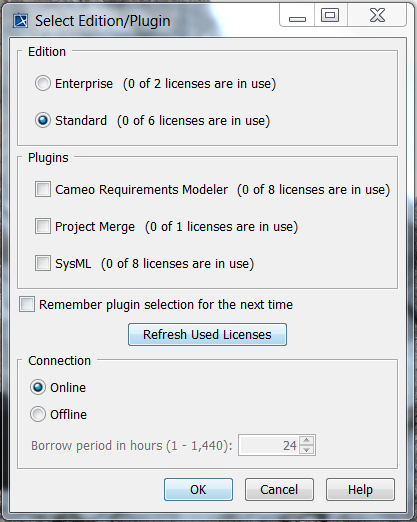
Figure 1 – Select edition and plug-ins dialog.
10.3.3. Switch to Fully Featured Perspective
In order to see all available MagicDraw/UML/SysML options, go to “Options” menu, “Perspectives” item, “Perspectives” sub-item, select the “Full Featured” option, and click on “Apply” button.
10.3.4. Creating UML Model compliant with COMODO Profile
It is possible to create a UML model compliant with COMODO Profile by executing the following steps:
Create a MagicDraw Project
Add comodoProfile to the Project
Create a <<cmdoModule>> Package
Create the Packages “Signals”, “Actions”, and “Activities” with all the events, actions, do-activities
Create a <<cmdoComponent>> Class with associated State Machine as behavior
Create States and Transitions for the State Machine
10.3.4.1. Creating MagicDraw Project
Use the “New” option of the “File” menu to:
Select the type of project “UML Project”
enter the SW module name (e.g. test) as project “Name”
select the “Project location” (e.g. test/config/model/)
as illustrated in Figure 2.
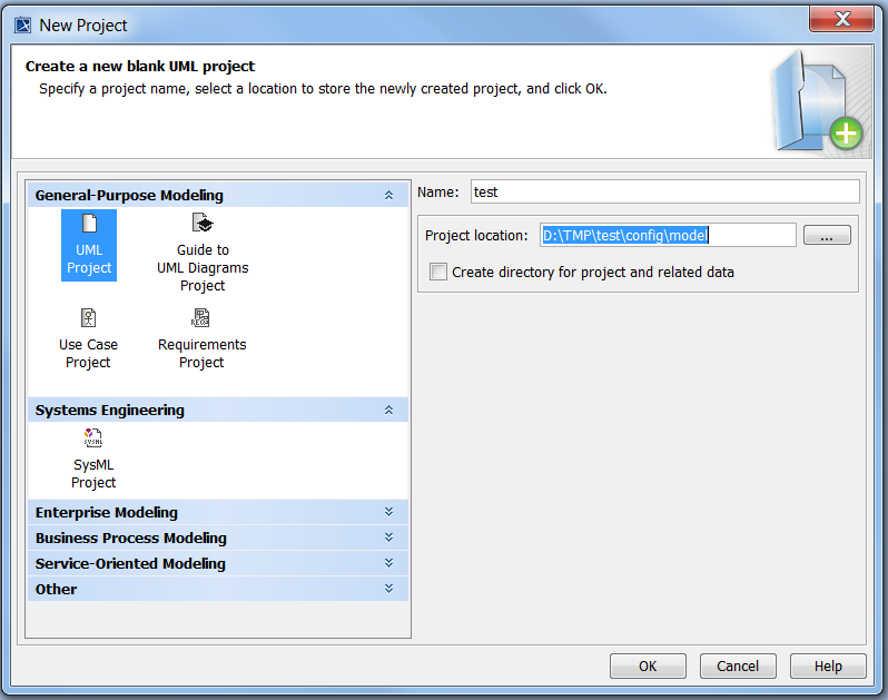
Figure 2 - Creating a new project.
10.3.4.2. Adding comodoProfile to the Project
Once the project is created, use the “Use Project …” option from the “File” menu, select “Use Project” item, “Use Local Project” or “Use Server Project” depending whether COMODO profile is loaded from local file or from the server.

select comodoProfile, and click on “Finish” button to load COMODO stereotypes (Figure 3).
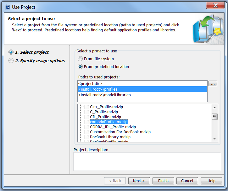
Figure 3 - Adding comodoProfile to a project.
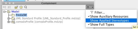
Note that in order to see the (COMODO) stereotypes applied to your modeling elements, click on the top-right corner of the “Containement” panel and select “Show Applied Stereotypes”.
10.3.4.3. Create a <<cmdoModule>> Package
Select the “Data” package in the “Containment” tab on the left side. With the mouse-right-click navigate through “Create Element” menu and select “Package” option as illustrated in Figure 4.
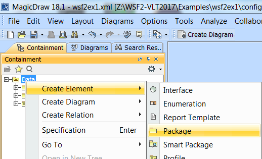
Figure 4 – Creating a Package.
Enter as Package name the name of the SW module (e.g. “test”).
Mouse-right-click on the newly created Package and select the “Stereotype” option. Select the “cmdoModule” stereotype and click on “Apply”. At the end it should look like in Figure 5.
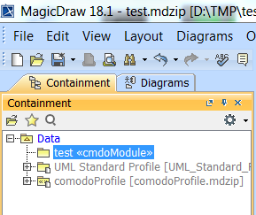
Figure 5 – Applying <<cmdoModule>> stereotype.
The package can be populated with signals, actions, activities, and the <<cmdoComponent>> class representing the SW component with associated classifier behavior.
10.3.4.4. Creating Signals
The events (such as commands, DB notifications, timers, file I/O, UNIX signals, and internal events) handled by the SW component are modeled via UML signals stereotyped by one of the COMODO stereotypes.
Signals can be grouped in a package called “Signals”. To create the package, right-click on the <<cmdoModule>> package and click on “Create Element” “Package” entering the package name “Signals”.
In order to create a signal, right-mouse click on the “Signals” package and select the option “Signal” from the menu “Create Element” as shown in Figure 6.
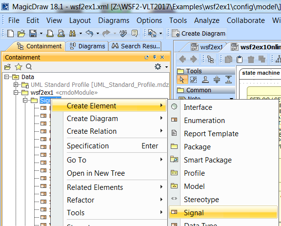
Figure 6 - Creating a new signal.
Once the signal has been created it should be named and the proper stereotype applied. The stereotype is applied by mouse-right-click on the newly created signal and by selecting the “Stereotype” option. comodoProfile offers the following stereotypes for Signals:
<<cmdoCommand>> for events representing commands received by the application (i.e. commands defined in the CDT).
<<cmdoInternal>> for events created by the application itself to trigger a transition.
<<cmdoNotificaiton>> for events representing changes of DB attributes.
<<cmdoTimer>> for events representing time-outs.
<<cmdoSignal>> for events representing UNIX signals.
<<cmdoFileio>> for events representing UNIX file I/O events.
Select the stereotype and click on the “Apply” button. After successful creation, the new signal should appear in the Signals package with the correct stereotype.
It is good practice to group the signals into a dedicated package.
10.3.4.5. Creating Actions
Statecharts actions are piece of code executed when entering/exiting a state (entry/exit actions) or when a transition is taken. Statecharts actions are modeled in UML with UML Activities. To create a UML Activity follow the instructions for creating a Signal (Creating Signals) and select the option “Activity” instead of “Signal”.
A Statecharts action is translated by COMODO into an invocation of a method of a class.
The name of the UML Activity should follow the convention: “GroupName.MethodName” where “GroupName” is the name of the class containing the method “MethodName”. The method GroupName::MethodName() is invoked by the State Machine engine when executing the model.
It is good practice to group all the actions into a dedicated package named “Actions”.
10.3.4.6. Creating Do-Activities
Statecharts Do-Activities are long lasting actions which are mapped to threads. In UML they are modeled with UML Activities. To create a UML Activity follow the instructions for creating a Signal (Creating Signals) and select the option “Activity” instead of “Signal”. The name of the UML Activity is translated by COMODO to the name of the class implementing the thread.
It is recommended to group all the do-activities in a UML Package named “Activities”.
10.3.4.7. Creating SW Components
A SW Component represents an application to be developed. In UML it is modeled by a UML Class with stereotype <<cmdoComponent>>. To create a Class follow the instructions for creating a Signal (Creating Signals) and select the option “Class” instead of “Signal”.
Once the Class has been created it should be named and the <<cmdoComponent>> stereotype applied. The stereotype is applied by mouse-right-click on the newly created Class and by selecting <<cmdoComponent>> from the “Stereotype” option.
10.3.4.8. Creating State Machine
In order to specify the behavior of a SW Component using a State Machine, mouse-right-click on the SW Component Class element, select “Create Diagram” option and click on “State Machine Diagram”. A State Machine with associated diagram will be created and assigned as classifier behavior to the SW Component.
10.3.4.9. Creating State Machine Diagrams
In order to create a new State Machine diagram, mouse-right-click on the State Machine element in the Containment tree, select the menu “Create Diagram” and the “State Machine Diagram” option. Rename the newly created diagram using F2 (or opening the Specification Dialog). Drag&drop from the Containment tree in to the diagram the states which are needed and should be specialized (Figure 7).
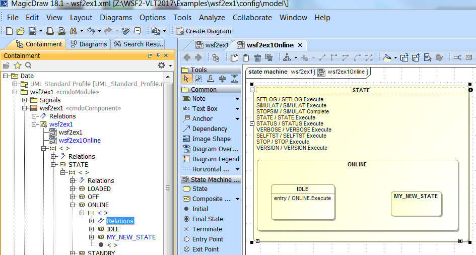
Figure 7 - New State Machine diagram and new sub-state.
10.3.4.10. Creating States
To create a new state, open the State Machine diagram and select, from the Tools, the type of state to create. Click in the diagram on the position where the state should be located. It is suggested to create Composite states (instead of leaf states) since they can be specialized.
The state must be named either by clicking on the state and typing the name or by opening the Specification Dialog and filling in the “Name” property.
Important: verify in the Containment tree whether the new state belong to the correct super-state (parent composite state). For example, in the Containment tree of Figure 7, the new state MY_NEW_STATE is a sub-state of ONLINE which in turn is a sub-state of STATE.
10.3.4.10.1. Initial Pseudo-state
Each composite state containing sub-states, must indicate the default initial active sub-state. This is done by drag&drop the “Initial” pseudo-state from Tools into the composite state and creating a transition from the “Initial” pseudo-state to the default initial sub-state.
Important: a composite state that contains sub-state must define a default initial state using the “Initial” pseudo-state.
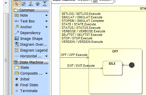
Figure 8 - Initial pseudo-state.
Figure 8 shows that the default initial state of the OFF composite state is IDLE.
10.3.4.10.2. Entry/Exit Actions
To specify an entry or exit action to be executed when a state is entered or exited simply drag the UML Activity (see section Creating Actions) and drop it on the state. A pop-up menu with the following three options will appear: Entry, Exit, Do activity. Select the “Entry” or the “Exit” option.
10.3.4.10.3. Do-Activities
To specify a Do-Activity to be executed while the application is in a given state, simply drag the UML Activity (see section Creating Do-Activities) and drop it on the state. A pop-up menu with the following three options will appear: Entry, Exit, Do activity. Select the “Do activity” option.
10.3.4.11. Creating Transitions
10.3.4.11.1. Normal Transition
Transition between two states can be create by clicking on the source state, selecting the “Transition” tool from the palette (Figure 9), and dragging the line to the destination state.
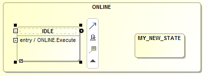
Figure 9 - Creating a transition between IDLE and MY_NEW_STATE state.
10.3.4.11.2. Self-Transitions
A self-transition is a transition where the source and destination state is the same. It can be created like a normal transition but selecting the “Self-transition” tool which is just below the “Transition” tool. Note that when taking a self-transition, the state is exited and reentered and therefore the exit/entry actions of the state, if defined, are executed.
10.3.4.11.3. Internal Transitions
An internal-transition is a transition where, like a self-transition, the state does not change. However, since in this case the state is never exited nor entered, the entry/exit actions are not executed.
To create an internal transition, open the Specification Dialog of the state and select on the left side the element “Internal Transitions” as shown in Figure 10. Click on “Create” button and enter the following properties:
Section “Transition” property “Name”: the name of the event/signal triggering the transition.
Section “Transition” property “Guard”: the name of the guard to be verified before executing the transition. Guards have the same syntax of actions: “ClassName.MethodName” (see section Creating Actions).
Section “Trigger” property “Event Type”: select the value “SignalEvent”
Section “Trigger” property “Signal”: select the name of the signal that should have been previously created and added in the Package “Signals” (see section Creating Signals).
Section “Effect” property “Behavior Type”: select the value “Activity”
Section “Effect” property “Name”: enter the name of the action using the syntax “ClassName.MethodName”.
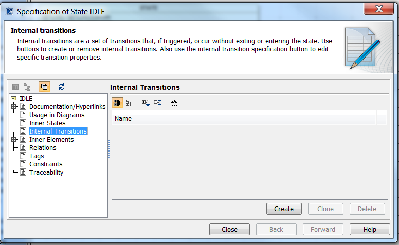
Figure 10 - Creation of internal transition for ONLINE/IDLE state.
10.3.4.11.4. Triggers
To specify the trigger (or event) of a transition simply drag from the Signal package the signal and drop it on the transition. Internal transitions are a special case, see section Internal Transitions.
10.3.4.11.5. Actions
To specify the action to be executed when a transition is taken simply drag from the Activity and drop it on the transition. Internal transitions are a special case, see section Internal Transitions.
10.3.4.11.6. Guards
To specify the guard to be evaluated before taking a transition, open the Specification dialog for the Transition and, in Section “Transition” property “Guard” enter the name of the guard. Guards name have the same syntax of actions: “ClassName.MethodName”.
10.3.4.12. Creating Orthogonal Regions
Statecharts orthogonal regions correspond to UML regions. By default, each UML state contains one UML region. To add an orthogonal region, mouse-right-click on the state and select the “Add New Region” option.
Figure 11 shows the result of adding a region to the ONLINE state of wsf2ex1 application. In the Containment tree within the ONLINE state the two unnamed regions are indicated with the symbol “< >”. Note that, in this example, the one that can be expanded is the region containing IDLE and MY_NEW_STATE sub-states, while the other one is the newly added region.
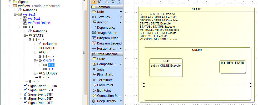
Figure 11 - Adding an orthogonal region to the ONLINE state.
Regions can be named by right-click them in the Containment tree and selecting the “Rename” option. The name of the regions can be displayed in the diagram by right-click on the state in the diagram and selecting the “Symbols Properties” option. Within the “Symbols Properties” dialog, check the box “Show Region Name” as shown in Figure 12.
Important: when two or more orthogonal regions are defined, they must always have a name.
Figure 12 shows on the left side the Containment tree with the two ONLINE regions named “Region1” and “Region2”. On the right side is the “Symbol Properties” dialog with the “Show Region Name” flag set to true. In the center is the diagram displaying the name of the regions.
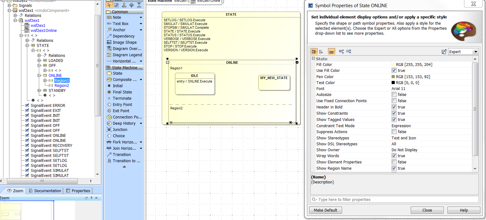
Figure 12 - Displaying the regions name of state ONLINE.
Important: events are broadcasted to all regions but they are processed sequentially one region after the other following the alphabetic order of the region name. In our example, events will be first processed in Region1 and then in Region2.
10.3.5. Loading, Saving and Exporting Models
10.3.5.1. Loading Models from File
A model can be loaded via the “Open Project …” option of the “File” menu and selecting the UML model to open. When loading a model that uses COMODO profile, MagicDraw will try to open also the profile. If comodoProfile.mdzip is not located in the Profile directory of MagicDraw installation, the tool will ask the user to locate the it.
10.3.5.2. Loading Models from Teamwork Server
A model archived in Teamwork Server can be loaded by:
Selecting the “Login” option from the “Collaborate” menu and entering the login information.
Selecting the “Open Server Project…” option from the “Collaborate” menu and clicking on the project to open.
10.3.5.3. Saving and Exporting Models
Modification to the model can be saved in the MagicDraw proprietary format (.mdzip format) using the “Save Project” option of the “File” menu. In order to use COMODO tool to generate artifacts, the model must be exported to the Eclipse UML2 XMI v.2 or above format (.uml) which is tool independent and a de-facto standard since supported by the majority of the modeling tools (e.g. all Eclipse Modeling Framework tools but also commercial tools). The option can be found under the “File” menu as illustrated in Figure 13.
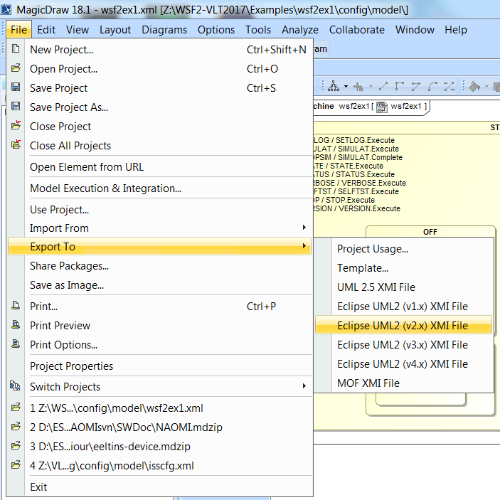
Figure 13 - Exporting to EMF XMI format.
After confirming the location of the exported model (e.g. wsf2ex1/config/model directory) and clicking on “Yes” button of the alert dialog asking permission to overwrite the existing (.uml) files, the model is converted and COMODO can be used to generate artifacts.
Important: MagicDraw format (mdzip) contains the model information and the graphical information (diagrams). Eclipse UML2 XMI (.uml) contains only model information.
Important: COMODO can be used only on SysML/UML models archived in Eclipse UML2 XMI format (.uml).
The save and export operation can be simplified by setting the configuration option that can be found in “Options” menu, “Environment”, “Eclipse UML2 (v2.x) XMI”, “Export Model to Eclipse UML2 XMI …” and selecting “Always export” value as illustrated in Figure 14. In this way, every time a model is saved, it is also exported to Eclipse UML2 XMI format.
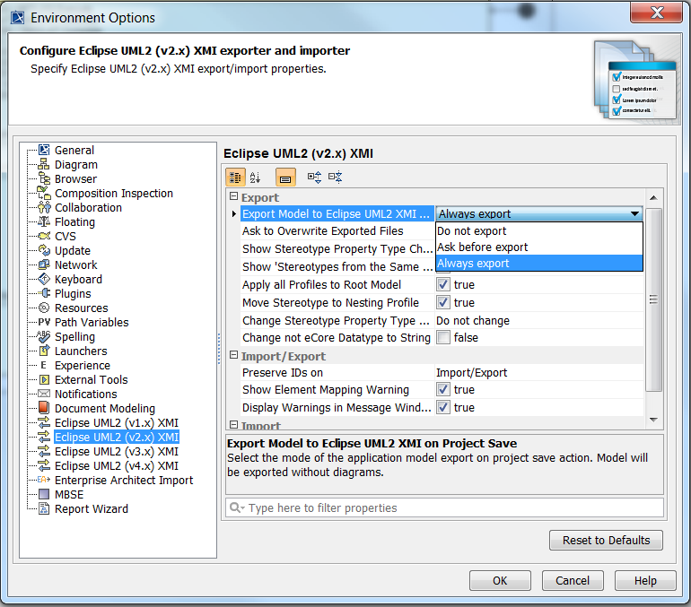
Figure 14 – Making Export to EMF XMI automatic.
10.3.6. Model-View
In MagicDraw, the screen is split into 4 main sections: left section, center section, right section and bottom section. The left section hosts the Containment tree (to navigate through all the model elements and relations), the center section hosts the Tools, the right section hosts the diagrams, while the bottom section (located below the first three sections) is used for logging purposes (info, errors, warnings, and validations information).
Important: The model consists of the elements and relations contained in the Containment tree. A diagram is only one possible view of the model.
Note that diagrams may display only some of the model elements/relations of the model.
Important: removing a model element from a diagram using the “Delete” key, does not delete the model element from the Containment tree. Instead using Ctrl-D will delete a selected element in the diagram also from the Containment tree. Another possibility is to select the element in the Containment tree and with the mouse-right-click select the “Delete” option: the element will be deleted from the model and from all the diagrams.
Figure 15 shows the Containment tree (left section), the Tools (center section), and the State Machine diagram (right section) after loading wsf2ex1/config/model/wsf2ex1.xml MagicDraw model. The Containment tree includes three Packages:
“UML Standard Profile” containing all UML stereotypes
“wsf2ex1” containing the model of wsf2ex1 application
“comodoProfile” containing COMODO stereotypes
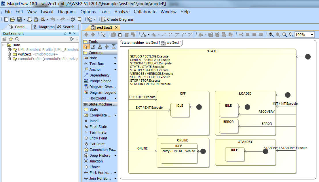
Figure 15 - Containment tree (left section), Tools (center section) and State Machine diagram (right section).
Figure 16 shows the content of the Package “wsf2ex1” in the Containment tree. Only the first two elements are used in the context of WSF2:
The Package “Signals” used to group all signals (i.e. events) used in the State Machine to trigger a transition.
The Class “wsf2ex1” with stereotype <<cmdoComponent>> which represents the application to be modeled. This class contains the State Machine which describes its behavior.
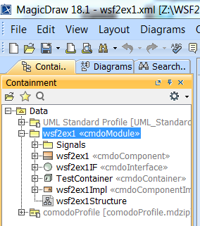
Figure 16 - <<cmdoModule>> Package’s content.
Figure 17 shows the signals (events) with their stereotypes included in the Package Signal (1) and used by the State Machine. It shows also the modeling elements representing: the State Machine (2), the State Machine diagram (3), the Transitions (4) and the States (5). Each composite state can be expanded; it contains its transitions and its sub-states. For example, STATE contains OFF, LOADED, ONLINE, STANDBY sub-states and the transitions from STATE to LOADED, etc.
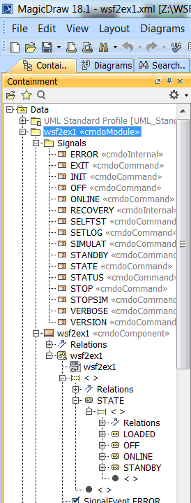
Figure 17 – Signals and State Machine model elements for wsf2ex1 applications.
10.3.7. Opening Diagrams and Specification Dialogs
To open a diagram, double click on the diagram in the Containment tree.
To open the Specification Dialog of a model element, double click on the element in the Containment tree (or select the element and mouse-right-click to select the “Specification” option).
Important: in the top-right corner of the Specification Dialog, make sure that “Properties: All” is selected to be able to see all UML properties (Figure 18).
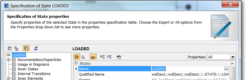
Figure 18 - Specification Dialog, all properties.