10. Alarm
Revision: |
|
|---|---|
Status: |
Released |
Repository: |
|
Project: |
ELT CII |
Folder: |
trunk/deliverables/phase9 |
Document ID: |
|
File: |
MAN_ELT_Alarm.docx |
Owner: |
Matej Šekoranja |
Last modification: |
January 28, 2021 |
Created: |
July 5, 2019 |
Prepared by |
Reviewed by |
Approved by |
|---|---|---|
Jernej Strniša (CSL) Matej Šekoranja (CSL SWE) |
Borut Terpinc (CSL SWE) Jan Pribošek (CSL SWE) |
Gregor Čuk (CSL) |
Revision |
Date |
Changed/rev iewed |
Section(s) |
Modificatio n |
|---|---|---|---|---|
1.0 |
6.5.2020 |
jstrnisa/bt erpinc |
All |
Document creation. |
1.1 |
5.7.2020 |
bterpinc |
4 |
Added plugin tab example |
1.2 |
15.10.2020 |
msekoranja |
All |
RIX updates |
1.3 |
17.11.2020 |
msekoranja |
4.3.2. |
Replaced ias-webserv ersender with iasWebServe rSender |
1.4 |
13.1.2021 |
jrepinc |
4.2 |
Alarm Configurati on GUI updates |
1.5 |
26.1.2021 |
jrepinc, msekoranja |
4.2 |
Alarm Configurati on GUI updates (RIXes PSI 19, PSI 21). Transfer function alarm priority paragraph added (PSI 39). |
Confidentiality
This document is classified as a confidential document. As such, it or parts thereof must not be made accessible to anyone not listed in the Audience section, neither in electronic nor in any other form.
Scope
This document is manual for the Alarm system used by ESO employees involved with the ELT Core Integration Infrastructure Software project.
Audience
This document is aimed at those Cosylab and ESO employees involved with the ELT Core Integration Infrastructure Software project, as well as other Users and Maintainers of the ELT Core Integration Infrastructure Software.
This document requires knowledge of IAS concepts in order to be comprehensible. Please read IAS architecture [2] and design [3] documents first.
Glossary of Terms
API |
Application Programming Interface |
|---|---|
CII |
Core Integration Infrastructure |
CLI |
Command Line Interface |
CDB |
IAS configuration database |
DP |
Data Point |
GUI |
Graphical User Interface |
ES |
ElasticSearch |
JSON |
Javascript object notation |
OLDB URI |
Online Database Uniform Resource Identifier |
SVN |
Subversion |
IAS DASU ASCE |
Integrated Alarm System Distributed Alarm System Unit Alarm System Computing Element |
IASIO |
Integrated Alarm System Input/Output |
References
ESO, Core Integration Infrastructure Requirements Specification, ESO-192922 Version 7
ESO, Integrated Alarm System Architecture, ESO-293482 Version 2
ESO, Integrated Alarm System Design, ESO-299387 Version 1
ESO, Integrated Alarm System General information, https://github.com/IntegratedAlarmSystem-Group/ias/wiki
Cosylab, ELT CII Online Database Transfer Document, CSL-DOC-19-176539, Version 1.7
Cosylab, ELT CII Configuration User’s Manual, CSL-DOC-19-173189, Version 1.7
Cosylab, ELT CII Online Database User’s Manual, CSL-DOC-19-176283, Version 1.3
https://github.com/IntegratedAlarmSystem-Group/ias/wiki/Transfer-functions-how-to
https://github.com/IntegratedAlarmSystem-Group/ias/wiki/Transfer-function-in-python
https://github.com/IntegratedAlarmSystem-Group/ias/wiki/ConfigurationDatabase
Cosylab, ELT CII Log user manual, CSL-DOC-20-181435, v1.5
10.1. Overview
This document is a user manual for CII Alarm service. It explains how to configure alarms using the CII Alarm Config GUI. It also explains how to inspect, address and acknowledge alarms using the IAS Web GUI.
This document requires knowledge of IAS concepts in order to be comprehensible. Please read IAS architecture [2] and design [3] documents first.
10.2. Introduction
CII Alarm system uses Integrated Alarm System (IAS) [4] as its alarm system. IAS is a software whose main purpose is to get alarms and monitor points from different sources and generate alarms to present to the users who can range from operators in the control room, up to engineers sittings at their desks. The alarm system is a message-passing facility that routes information about abnormal situations detected from hardware or software to the user. For IAS architecture and design please refer to the IAS architecture [2] (necessary to read to get to know IAS concepts) and design [3] documents.
IAS is based on pluggable architecture to integrate with external systems. To connect the IAS to the CII, CII-IAS bridge needed to be developed. The bridge consists of the following components (Figure 2‑1):
OLDB Plugin - The long-running process that reads from OLDB and writes to IAS (Kafka).
OLDB Sink - The long-running process that reads from IAS (Kafka) and writes to OLDB.
CII-CDB Adaptor – The implementation that provides IAS access to the CII configuration database.
CII-IAS Config Exporter - The executable that is run before the IAS Alarm GUI webserver is started. It exports alarm related configuration from CII Config to IAS JSON files, as the webserver can only read configuration from JSON files.
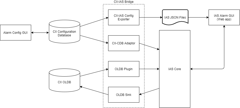
Figure 2‑1 CII Alarm System elements
To ease the creation of the configurations for the IAS, Alarm Config GUI can be used. Table 1 contains a brief explanation of the configuration elements used in Alarm Config GUI. For the proper explanation of the elements, refer to the IAS documentation [2], [3], [4].
Table 1: Alarm system elements
Entity Name |
Description |
|---|---|
ASCE |
An alarm system computing element that runs inside DASU and contains one transfer function. |
DASU |
An alarm system element that runs inside Supervisor and contains one or many ASCEs. |
IASIO |
An alarm system input/output entity. |
Supervisor |
A standalone process that contains one or many DASUs. |
Transfer Function |
A transformation function that calculates alarm states. It receives and outputs IASIOs. |
Plugin |
A plugin for IAS system that interfaces the IAS system with external systems (in CII case OLDB). |
10.3. Prerequisites
This section describes the prerequisites for using the CII Alarm service. Note that the preparation of the environment (i.e. installation of required modules, configuration, running of services) is not in the scope of this document. Refer to the CII Alarm system TRD document for detailed information on how to establish the environment for usage of CII Alarm service.
10.3.1. Required modules
For using the CII Alarm service, the following components must be installed on the system (IAS environment):
IAS
CII-IAS bridge
Contains of cii-ias-bridge WAF module and depdendant CII libraries.
Since IAS environment does not have WAF installed the cii-ias-bridge module is built on DevEnv and copied to IAS environment together with depdendant CII libraries.
For using the CII Alarm config GUI for the following WAF modules must be installed on the system (DevEnv):
elt-qt-widgets
alarm-config-gui
For testing activating the alarms using the alarm example scripts, one more WAF module must be built and installed (DevEnv):
alarm-examples
10.3.2. Services
To use the CII Alarm service, the following services must be accessible from the system running the IAS:
Configuration service:
CII Alarm service uses the CII Configuration service for the alarm structure configuration and alarm storage.
OLDB service:
CII Alarm service uses the CII OLDB services to manage alarms. Alarm service also subscribes and monitors OLDB datapoints.
10.4. Alarm Usage Examples
This section goes through a simple example of how to configure, inspect, and handle the alarms generated by the CII Alarm service. The example will follow a simple workflow:
An input data point will be created in the OLDB.
The Alarm service will be configured so that the created data point will be monitored.
A new value will be written to the data point so that the alarm will be activated.
Alarm will be viewed in the alarm web service and will be acknowledged and shelved.
10.4.1. Creating the Input Data Point
CII Alarm service subscribes to OLDB data points. These are input values to the alarm service. The CII Alarm service also generates alarm OLDB data points (output data points) to store the alarm state. The names of the input and output data points are defined in IASIO configuration. The actual behavior of the alarm is defined by the IAS transfer function and proper ASCE and DASU configuration. Consult [2] and [4] for more information.
While the alarm state data points are generated by the Alarm service, the input data points are not generated automatically and must be created in the OLDB.
The simplest way to create the input data point for this example is to use the create-alarm-input.sh script which is located in alarm-examples project root folder.
create-alarm-input.sh
Calling this script with no parameters will create an INT32 type data point with URI cii.oldb:/alarmtest/device/motor/input_int_dp and initial value 0. Note that the script also accepts three parameters to create any other numeric type data point for other use cases.
uri – URI of the new data point
type – a type of the new data point. It must be one of the numeric types defined in [7].
value – initial value of the data point. It must correspond to the provided type
The following example call is equivalent to the call without parameters
create-alarm-input.sh uri:cii.oldb:/alarmtest/device/motor/input_int_dp type:INT32 value:0
Input data points can also be created in two other ways:
Using the OLDB GUI application
Using the OLDB API
Detailed instructions on how to create data points are not in the scope of this document. They are explained in detail in [7].
For this example, a data point of type INT32 must be created with the following URI:
cii.oldb:/alarmtest/device/motor/input_int_dp
The data point should have value 0 at the start of this example.
10.4.2. Configuring the Alarm Service
The CII Alarm service must be configured so that input data points can be monitored. The configuration includes the input data points, which ASCEs and DASUs exist in the Alarm system, and respective transfer functions that define what kind of alarm data points are generated by the system. For a detailed description of the Alarm system architecture consult [2], and for all details on alarm configuration attirbutes see [4][12].
The configuration in this example will be done with the CII Alarm GUI application. To run the Alarm GUI application run:
alarm-config-gui
The GUI window should open as seen in Figure 4‑1.

Figure 4‑1: Alarm GUI main tab
To enable write operations, check out the Write enabled checkbox in the Options menu option (Figure 4‑2).
To reload data for the current tab from the database, click the Refresh button. Note that any unsaved data might be lost. If you click on the Refresh button and unsaved changes are detected a dialog box is shown. You have three options to select from:
Save: saves unsaved changes and continues with refresh (if this button is disabled, enable the Write Enabled option)
Discard: discards unsaved changes and continues with refresh
Cancel: keeps unsaved changes and cancels refresh
To verify the consistency of the data saved into the remote database, click the Verify button.
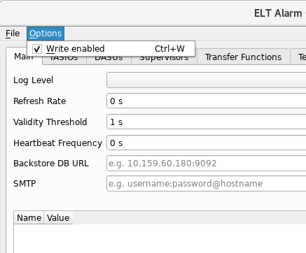
Figure 4‑2: Enabling write operations to the configuration service
10.4.2.1. Definfing general settings
General settings can be set on the main tab. Set LogLevel, refresh rate, etc… according to the values shown in Figure 4‑1.
10.4.2.2. Defining IASIOs
IASIOs are input and output entities of the Alarm system. To define a new IASIO go to the IASIOs tab and click on the + button (Figure 4‑3). To duplicate an existing IASIO click the = button.
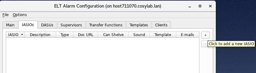
Figure 4‑3: Adding a new IASIO
A new item appears in the table. In the IASIO cell write the URI of the input data point. Write the relative path alarmtest/device/motor/input_int_dp of the input data point cii.oldb:/alarmtest/device/motor/input_int_dp (Section 4.1) and set the Type of data point to INT.
Create another IASIO for the output alarm. The motor/input_int_dp_alarm in the IASIO cell and set the Type to ALARM. Then set the value under the Can Shelve column to true.
Other cell values for both IASIOs can be left empty or with default values if any (Figure 4‑4), as the fields description, documentation URL and e-mails are optional and provide only additional information on IASIO. Also keep in mind, the fields Can shelve, Sound, and E-mails are only applicable to IASIOs of type ALARM. Template field allows templatization of the IASIO that is not used in this basic example (refer to IAS documentation on templatization). At the end click on the Save button.
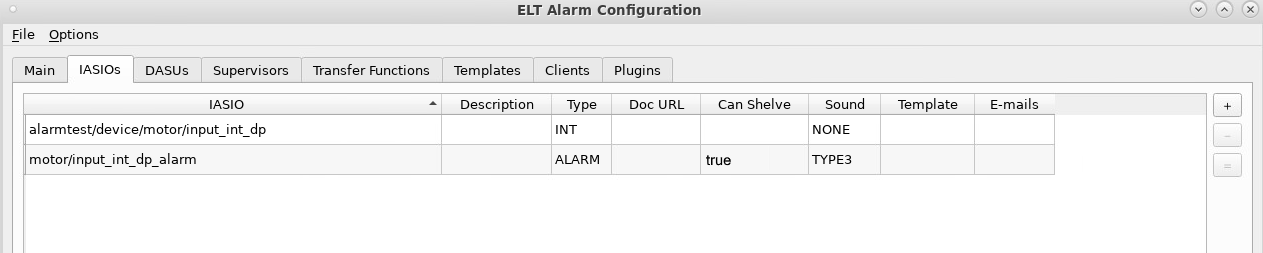
Figure 4‑4: Input and Output IASIOs configuration
10.4.2.3. Importing a Transfer Function
Alarm system output IASIOs are calculated by Transfer Functions. Transfer functions are in the IAS domain and must be implemented and built there. IAS already provides a small set of Transfer functions. Please refer [8] to [9] and for details on Transfer functions. To import a new transfer function, go to the Transfer Functions tab and click on the + button. To duplicate an existing transfer function click the = button.
For this example write org.eso.ias.asce.transfer.impls.MinMaxThresholdTF in the Class column and choose SCALA in the Language column (Figure 4‑5). The MinMaxThresholdTF function activates the alarm when the value of the input data point goes above or below defined limits.
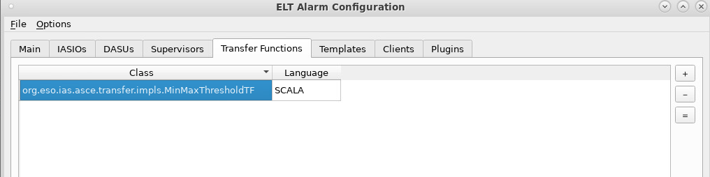
Figure 4‑5: Importing new Transfer Function
Finally, click on the Save button to commit the configuration.
10.4.2.4. Defining DASUs
DASUs are containers for ASCE entities, that make alarm calculations using the Transfer functions. First DASU needs to be defined followed by its ASCE(s) with Transfer function to be used.
To define a new DASU, go to the DASUs tab and click on the + button next to the DASU table (the topmost table). To duplicate an existing DASU click the = button.
Set the name if the DASU in the cell under the DASU column to int_alarm_dasu. Leave the other cells empty for the time being (Figure 4‑6) – default logging level will be used and there will be no templatization of the DASU.

Figure 4‑6: The DASUs tab
Define a new ASCE and set the name (the cell under ASCE column) to int_alarm_asce. To do that click on the + button next to the top table in the Contained ASCEs panel. To duplicate an existing ASCE click the = button. In the Transfer Function column choose the transfer function defined in section 4.2.3. In the Output column enter the output IASIO defined in the section 4.2.1, i.e. motor/input_int_dp_alarm. In the DASU column write the name of the DASU defined above (Figure 4‑7). i.e. int_alarm_dasu.
In the Inputs table add input by clicking the + button and select the IASIO name alarmtest/device/motor/input_int_dp to be (the only) input of the ASCE. In the Properties table add two upper limits for the input datapoints by clicking on the + button next to the table:
org.eso.ias.tf.minmaxthreshold.highOn with value 5: the alarm is activated if the value of the input data point is higher than 5.
org.eso.ias.tf.minmaxthreshold.highOff with value 1: If the alarm is activated and the value of the input data point goes under 1, the alarm is deactivated.
Note that analogous lower limits minmaxthreshold.highOff and minmaxthreshold.highOn can be defined. If both upper and lower limits are defined in the same ASCE, the alarm will not distinguish between the input value going above or below the limits. If we want to distinguish between these two cases, we need to define two ASCE with the same input, one checking for the high value and the other checking for the low value.
Alarm priority is determined by the Transfer function. Some implementations allow the priority to be configurable, e.g. org.eso.ias.asce.transfer.impls.MinMaxThresholdTF has a property named org.eso.ias.tf.alarm.priority for that reason. Valid values are: SET_CRITICAL, SET_HIGH, SET_MEDIUM (default), SET_LOW.
To add the ASCE to deploy in the DASU, write the ASCE name in the ASCEs column of the DASUs table (Figure 4‑7), i.e. int_alarm_asce.
To define output of the DASU, in the DASU table select one output among IASIO(s) output(s) deployed within the DASU as defined in section 4.2.1 in the Output column (Figure 4‑7), i.e. motor/input_int_dp_alarm.
Finally, click on the Save button to commit the configuration.
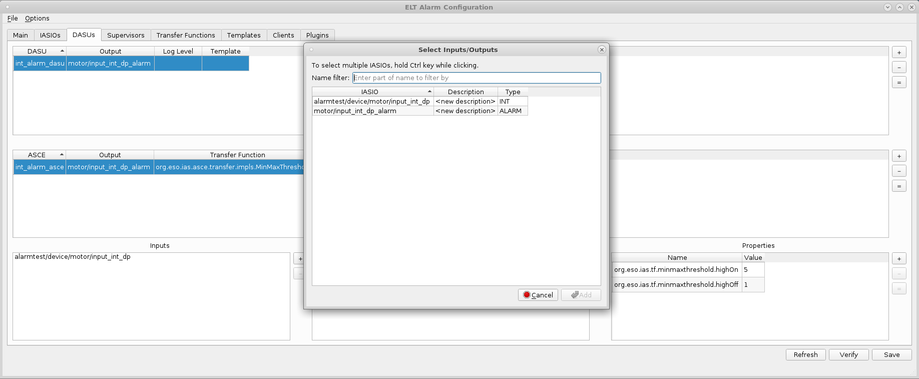
Figure 4‑7: Defining DASU
10.4.2.5. Defining the Supervisor
To deploy DASUs we need to define a Supervisor first. Supervisor is a stand-alone process that hosts DASUs among with its ASCEs including needed Transfer Function processing.
To define a new Supervisor, go to the Supervisors tab and click on the + button next to the topmost table. To duplicate an existing supervisor click the = button. Name the new supervisor test_supervisor and assign the hostname localhost to it (Figure 4‑8).
In the “DASUs to Deploy” table add a new DASU and select the one defined in section 4.2.4., leave Template and Instance column empty, meaning DASU will not be processed as a template. To make an empty instance column, click on the mouse right button and select clear.
The Template column defines what template to apply and Instance column defines instance number used to apply when processing the template. For more information on templates refer to the IAS documentation.
The shortcut to DASU is provided by right-clicking on the DASU column and then clicking on the “Go to DASU”.
Finally, click on the Save button to commit the configuration.

Figure 4‑8: Defining a new supervisor
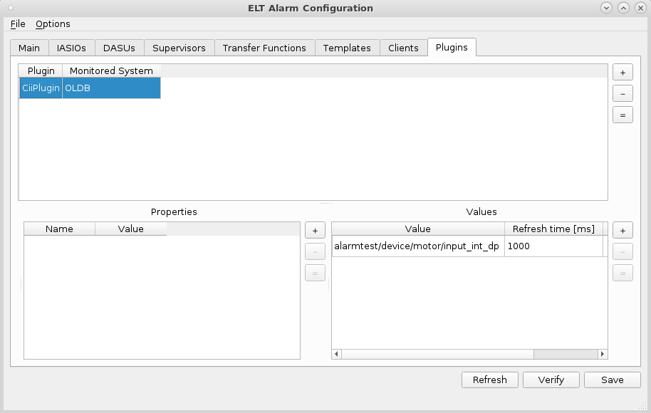
10.4.2.6. Defining the Plugin
OLDB Plugin also needs to be properly configured, especially a set of OLDB data points to be monitored by the particular Plugin instance.
To define a new Plugin, go to the Plugins tab and click on the + button next to the topmost table. To duplicate an existing plugin click the = button. Name the new plugin “CiiPlugin” and set the monitored system “OLDB”. Values table defines a set of data points to monitor. Assign a new monitored value under the Values table by clicking on the + button. Double click the Value column and select the desired input. If needed change the “Refresh time” (for how long a value is valid if not updated) or other attributes. (Figure 4‑9).
Finally, click on the Save button to commit the configuration.
Figure 4‑9: Defining the plugin
10.4.3. Running the Alarm service
When the alarm configuration is in place the CII Alarm service should be started on an IasEnv system. The CII alarm system TRD and the CII-IAS bridge module contain the instructions on how to start the IAS services and CII-IAS bridge. The IAS environment must be able to access the CII system (e.g. through SSH).
10.4.3.1. Alarm Services
To start the Alarm services run the following commands on IasEnv:
# Run OLDB plugin (reads datapoints from OLDB)
$ iasRun -l j elt.ias.plugin.EltOldbPlugin CiiPlugin -cdbClass elt.alarm.config.CdbReaderImpl &

# Run OLDB sink (writes alarm states back to OLDB)
$ iasRun -l j elt.ias.sink.IasAlarmsConsumer localhost:9092 -cdbClass elt.alarm.config.CdbReaderImpl &

# Run IAS Converter (internal IAS process)
$ iasConverter Converter -cdbClass elt.alarm.config.CdbReaderImpl &

# Run Supervisor instance named test_supervisor
$ iasSupervisor test_supervisor -cdbClass elt.alarm.config.CdbReaderImpl &

# Run CII service that allows CII Alarm Configuration GUI to verify configuration
$ python verify-proxy.py &
Command-line parameter -cdbClass elt.alarm.config.CdbReaderImpl instructs to use implementation that uses CII configuration database instead of default IAS configuration, i.e. JSON files.
CII Alarm service (bridge) will read the configuration created in section 4.2 and used the defined structure in the IAS. The system should now be set to monitor input data points.
To be able to inspect and handle activated alarms the IAS webserver and display service must be started on IasEnv.
10.4.3.2. Running Web Server and Display Service
IAS Alarm GUI (aka IAS Display Service) is implemented as a web application, details on IAS web applications can be found here [11].
Before running the ias-webserver, make sure that the required environment variables are set
$ cat << EOF > .env
# undefined defaults to this
DB_ENGINE=sqlite
# env.var. used by iasWebServerSender
WS_CONNECTION_PASS=dev_pass
# env. var. used by webserver, WS_CONNECTION_PASS == PROCESS_CONNECTION_PASS, defaults to "dev_pass"
PROCESS_CONNECTION_PASS=dev_pass
DJANGO_SECRET_KEY=hidden_50chars_string_for_real_production
# env. var. used by webserver, SECRET_KEY == DJANGO_SECRET_KEY
SECRET_KEY=hidden_50chars_string_for_real_production
ADMIN_PASSWORD=admin
OP_DUTY_PASSWORD=op
REDIS_HOST=localhost
EOF
Documentation on environment variables used by the ias-webserver can be found here [10].
Note: REDIS_HOST points to a local IAS REDIS instance, not CII REDIS used for OLDB. It is being used by ias-webserver internally.
iasWebServerSender is a process needed by ias-webserver. It reads IAS internal Kafka topic and posts data to web server via WebSockets.
Enter the directory where the ias-webserver is installed. Then start the Redis server, export the alarm configuration and start the ias-webserver.
$ cd ias-webserver

$ redis-server –-protected-mode no &

# webserver reads configuration from JSON files,
# export/convert alarm configuration from CII configuration to JSON files
$ iasRun -l j elt.alarm.config.CdbConverter export .

# Run webserver within docker, sudo being used to allow starting a docker
$ sudo docker run --env-file .env -v $PWD/CDB:/usr/src/ias-webserver/CDB:z --net host webserver_image ./runserver.sh

# configure and run iasWebServerSender
$ export WS_CONNECTION_PASS=dev_pass

$ iasWebServerSender web-sender -cdbClass elt.alarm.config.CdbReaderImpl &
To run the IAS display service, enter the directory where the ias-display is installed and run the following command:
# Run display service within docker, sudo being used to allow starting a docker
sudo docker run --net host display_image ./runserver.sh
10.4.3.3. Activating Alarms
With CII Alarm system configured and running, the input data point can be written so that the alarm is activated. The easiest way to activate the alarm in this example is to use the activation script in the alarm-example project. To activate this alarm just run the activate-alarm.sh script in the root of the project
./activate-alarm.sh
This script will with no parameters write a value 8 to /alarmtest/device/motor/input_int_dp datapoint. It can however receive an uri and value parameter to be used for other numerical data points. The following example call does the same as calling the script with no parameters:
./activate-alarm.sh uri:cii.oldb:/alarmtest/device/motor/input_int_dp value:8
Another way to write to data points is to use the oldbWrite CLI tool that comes with oldb-client module.
oldbWrite /alarmtest/device/motor/input_int_dp 8
Users can also write to the data point using either the OLDB GUI or OLDB API. Consult [7] on how to use OLDB GUI, OLDB API and OLDB CLI applications.
Writing value 8 to the input data point as defined in this example will:
write value to the OLDB,
OLDB plugin will receive value change notification and forward updated value to the IAS,
ASCE will recalculate transfer function using updated value and will trigger an alarm,
OLDB sink will be notified about the alarm state change and will write the state back to a corresponding OLDB data point, e.g. motor/input_int_dp_alarm.
10.4.3.4. Inspecting Acknowledging Shelving
To inspect the alarms open the IAS web GUI in the browser. The address should be http://iashost:4200 where iashost is the hostname of the IasEnv system where the Alarm service is running.
After logging in the IAS alarm GUI go to tabular view by clicking on the table icon on the left (Figure 4‑10).
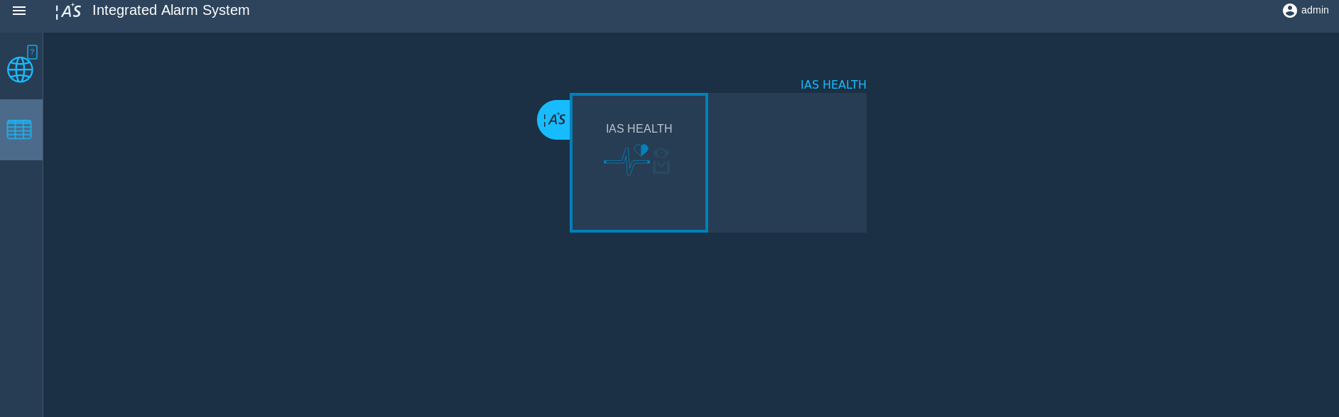
Figure 4‑10: IAS web GUI welcome page
In the tabular view there should be an alarm entry with name “motor/input_int_dp_alarm”. If there are more alarms they can be filtered by entering part of the name in the search bar above the table (Figure 4‑11).
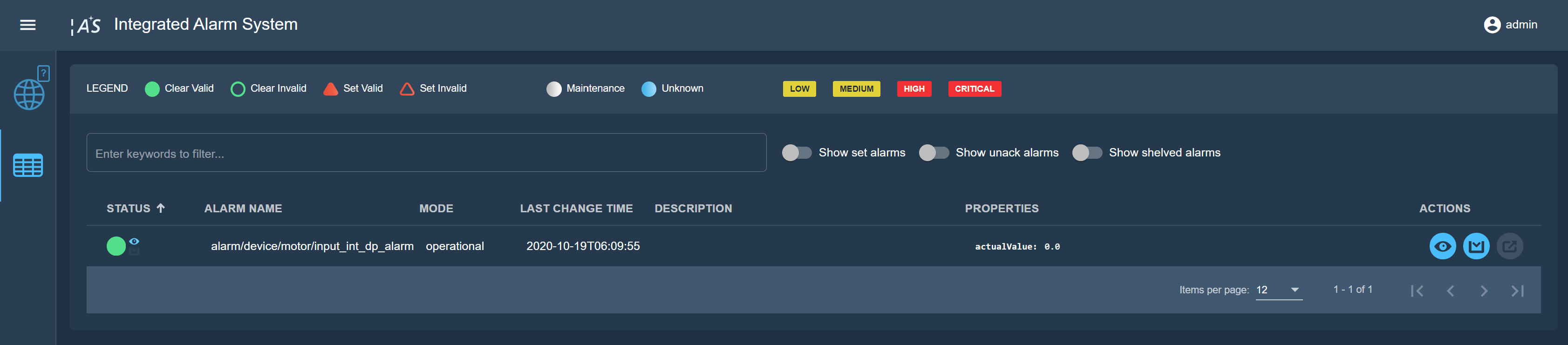
Figure 4‑11: Tabular view in IAS web GUI
To acknowledge the alarm, click on the “acknowledge” button in the ACTIONS cell of the entry. A popup window should open on the right side (Figure 4‑12). To acknowledge an alarm, a user with appropriate permissions must be entered. See section 5.1 on how to create a new user and give them permissions. The description of actions to be taken must also be entered. At the end tick the alarm “motor/input_int_dp_alarm” checkbox and click on the Acknowledge button.
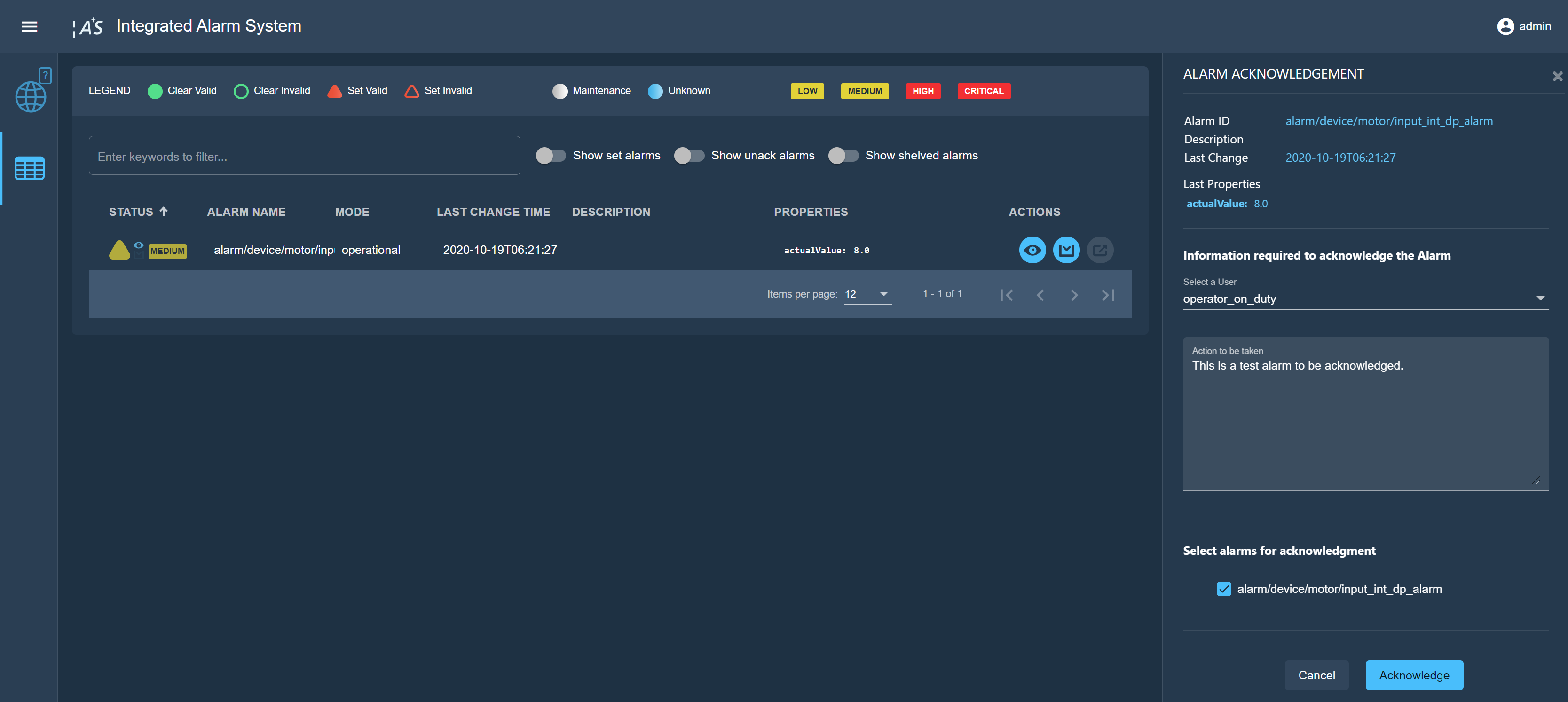
Figure 4‑12: Acknowledging an alarm
To shelve an alarm, click on the “shelve” button in the ACTIONS cell of the entry. A popup window should open on the right side (Figure 4‑13). To shelve an alarm, a user with appropriate permissions must be entered. See section 5.1 on how to create a new user and give them permissions. The reasons for shelving and shelve duration must also be entered. In the end, click on the Shelve button.
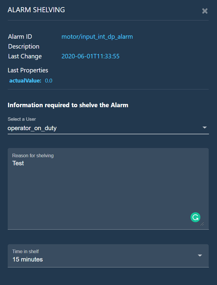
Figure 4‑13: Shelving an alarm
10.5. Advanced
10.5.1. Creating an IAS User
IAS web application administration can be done using Django administration console (http://iashost:8000/admin). The service is started with ias-webserver. To create a new user, click on the Add link in the Users section (Figure 5‑1).
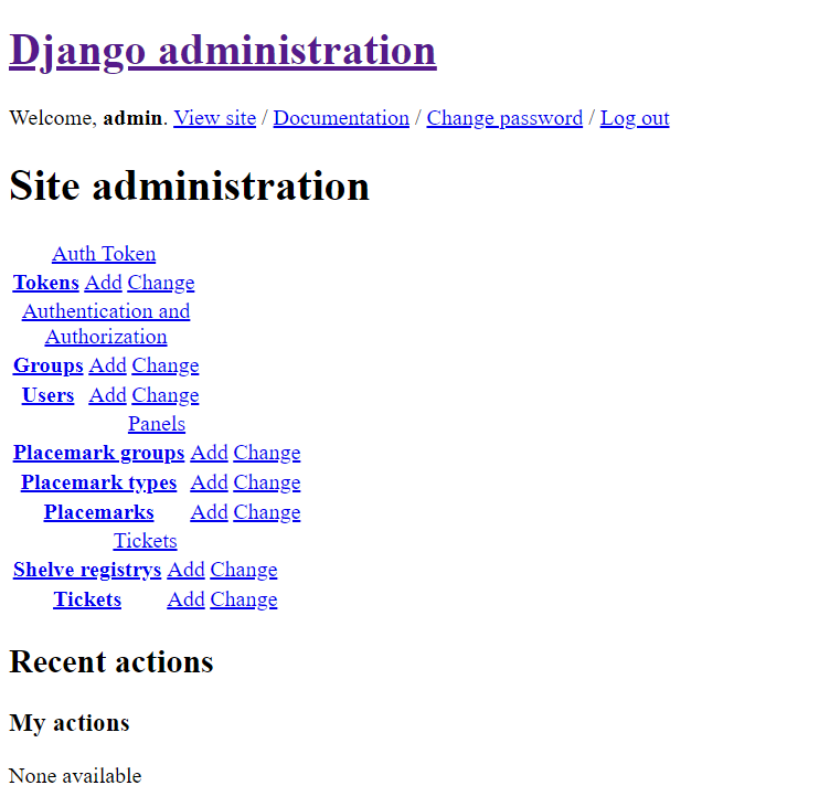
Figure 5‑1: IAS admin site first page
At “Add user” page (Figure 5‑2), enter the new user’s name and password, Then click on the Save and continue editing button. On the “Change user” page different information can be entered about the user. To add certain permissions (e.g. acknowledging, shelving alarms), scroll down to the Permissions section (Figure 5‑3) and add appropriate permissions by clicking on the Add button next to the Groups table and choose desired permissions or just checkout the Superuser status checkbox to give the user all permissions.
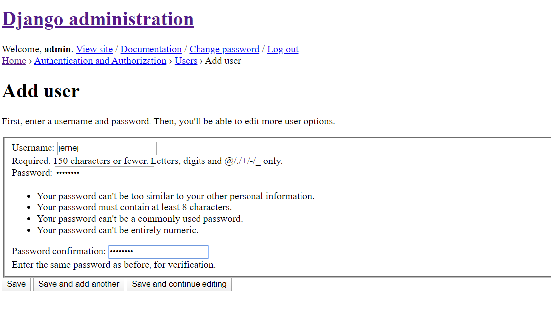
Figure 5‑2: Add user page
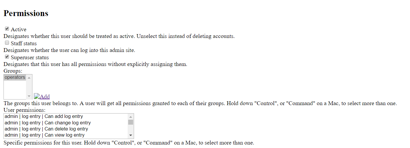
Figure 5‑3: Permissions section of the Change user page
10.5.2. Logging
For logging purposes, the CII-IAS Bridge components are using CiiLogManager which is configured through logging configuration file. For more information about logging and possible configuration options, see the CII Log user manual [13].
For IAS Core logging configuration refer to the IAS documentation [4].