|
|
 |
| |
| QC
PLOTS |
| |
CURRENT |
HISTORY |
| dark level |
 |
 |
| readout noise |
|
|
| hot pixel |
|
|
| QC1
database (advanced users): browse
| plot |
Click on CURRENT
to see the current trending (Health Check).
Click on HISTORY
to see the historical evolution of the trending. |
The IRDIS NIR detector is operated in cube mode and in nondestructive readmode (DET.READ.CURNAME=Nondest). All NDIT sub integrations are resolved and are stored in a cube frame with NDIT (~10), NAXIS=3 and NAXIS3=NDIT, meaning a cube frame with NDIT planes of with 2048x1024 pixel. Detector characteristics are monitored via three raw types: DARK, BACKGROUND and GAIN calibrations. DARK frames and GAIN calibrations are used to monitor the health of the detector, while BACKGROUND calibrations are used in the cascade to calibrate science data
| top
dark level and hot pixel |
 |
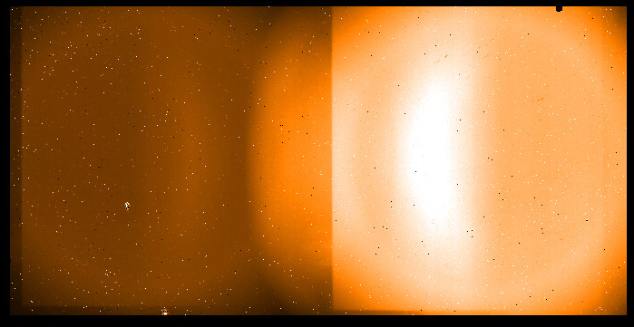
IRDIS raw dark frame with DIT=30 sec, averaged over NDIT=15 sub integrations. |
IRDIS dark frames are taken in regular intervals for the following setups
- DIT=2sec, NDIT=40
- DIT=8sec, NDIT=25
- DIT=30sec, NDIT=15
In addition dark frames are also acquired with the DIT and NDIT of the science observations.
The darks come as a single frame with one cube (NAXIS=3).
QC1 parameters
| parameter |
QC1 database: table, name
|
procedure |
| dark level |
sphere_irdis_dark, qc_med |
The pipeline uses the median dark level of the raw frame cube in ADU |
| ron |
sphere_irdis_dark, qc_ron |
The QC script calculates for each pixel the rms over the sample of NDIT=6..10, meaning of the second five planes of the raw frame cube. |
| number of hot pixel |
sphere_irdis_dark, qc_num_hotpix |
number of hot pixel, for details, see the pipeline user manual |
Dark frames are taken with INS1.OPTI1.NAME=CLOSED to measure the detector dark current, while IRDIS background calibration frames are acquired with INS1.OPT1.NAME=OPEN to measure the instrumental background.
Trending
Dark level and number of hot pixel is monitored for the three mentioned acquired health check setups.
History
From 2017-12-01 on the RON is based on the v0.28 version pipeline recipe. Values are about 1% lower with respect to the pre 2017-12 values obtained froma QC script.
| top instrumental background |
Dark frames are taken with INS1.OPTI1.NAME=CLOSED to measure the detector dark current,
while IRDIS background calibration frames are acquired with INS1.OPT1.NAME=OPEN to measure the instrumental background. The background frames come as a single frame with one cube (NAXIS=3).
 |
IRDIS raw background frame with DIT=30 sec, averaged over NDIT=15 sub integrations for the D_K12 dual beam filter. Image cuts -5 and 1000 ADU |
IRDIS background calibration frames are acquired with the same DIT and and NDIT as the dark frames, but with INS1.OPT1.NAME=OPEN. The background is dependent on the set of used filters:
CPI neutral density filter (IN4.FILT2.NAME = OPEN, or ND_2.0, or ...)
IRDIS broad band filter (INS1.FILT.NAME = B_H or B_Y or ...)
IRDIS dual beam filter (INS1.OPTI2.NAME = CLEAR or D_H12 or ...)
QC1 parameters
| parameter |
QC1 database: table, name |
procedure |
| background rate |
SPHERE_irdis_background, qc_backrate
|
The pipeline returns the median level of the raw frame cube divided by DIT |
Trending
The background rate (in ADU/sec) is monitored for the DBI modes only (INS1.OPTI2.NAME != CLEAR).
As can be seen on the health check plot , the background in the H-band is stable with about 0.13 ADU/sec (upper left box) and shows a larger scatter for the K-band at 17 ADU/sec (upper right box).
The lower right box shows the K-band background when there is a neutral density filter in the CPI (large back and blue symbols).
In this configuration the measured background follows the temperature of the neutral density filter. The black, blue and green symbols show the mesred background rate, while the red small symbols show the scaled temperature sensor value and demonstrates the correlation.
The following scaling is used for the temperature sensor INS4.TEMP449.VAL located in the common path interface:
T(in the plot) = 1.452 * T - 1.409
|
