|
|
 |
| |
| QC
PLOTS |
| |
CURRENT |
HISTORY |
| IMG bias |
 |
 |
| IMG ron |
|
|
| IMG dark |
|
|
| |
|
|
| POL bias |
|
|
| POL ron |
|
|
| POL dark |
|
|
| QC1
database (advanced users): browse
| plot |
Click on CURRENT
to see the current trending (Health Check).
Click on HISTORY
to see the historical evolution of the trending. |
The ZIMPOL optical CCDs are operated synchroneously in a special shift-and-add mode (see the User Manual and the pipeline user manual for details). ZIMPOL has two detectors (DET.CHIP.NAME= Callas and Bartoli), each one with 1156 x 2014 pixel. Raw frames come with two extensions, for each detector one fits cube. ZIMPOL detectors can be operated in one of the three modes (DET.READ.CURNAME) StandardImaging, SlowPolarimetry and FastPolarimetry.
 |
 |
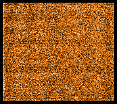
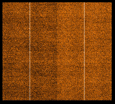
ZIMPOL raw bias frames (one plane of the cube) in StandardImaging readmode. Left is for Callas and right is for Bartoli. |
 |
 |
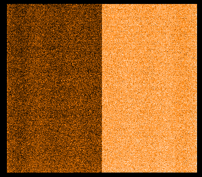
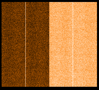
ZIMPOL raw bias frames (one plane of the cube) in SlowPolarimetry readmode. Left is for Callas and right is for Bartoli. |
 |
 |
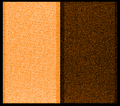
ZIMPOL raw bias frames (one plane of the cube) in FastPolarymetry readmode. Left is for Callas and right is for Bartoli. |
QC1 parameters
| parameter |
QC1 database: table, name
|
procedure |
| bias |
sphere_zimpol_bias_img, qc_bias
sphere_zimpol_bias_pol, qc_bias
|
median of the first plane of the raw fits cube in ADU |
| ron |
sphere_zimpol_bias_img, qc_ron
sphere_zimpol_bias_pol, qc_ron |
The first five planes of the data cube are considered. For each pixel the standard deviation out of the five planes is calculated. The median of all stdev values between x=[300,850] and y=[100,900] is taken. |
| rms |
sphere_zimpol_bias_img, rms_I_CAM1, rms_P_CAM1, rms_I_CAM2, rms_P_CAM2
sphere_zimpol_bias_pol, rms_zero_odd, rms_zero_even, rms_pi_odd, rms_pi_even |
rms of the bias product frame. |
Trending
bias, ron and rms are trended for
- for both detectors (CAM1 and CAM2)
- in imaging mode for both cycles (I and P).
- in polarimetry mode for all four cycles (phase zero odd subcycle, phase pi odd subcycle, phase pi even subcycle, phase zero even subcycle).
Optical dark frames are acquired once a month in all three read modes to monitor the dark radiation. The exposure time is 100 asec.
QC1 parameters
| parameter |
QC1 database: table, name |
procedure |
| dark level |
sphere_zimpol_dark_img, median_I_CAM1, median_P_CAM1, median_I_CAM1, median_P_CAM2
sphere_zimpol_dark_pol,
median_zero_odd, median_pi_odd, median_pi_even, median_zero_even
|
dark level after 100 sec |
Trending
In imaging mode the QC parameters come per CCD (CAM1, CAM2) and per phase (I, P). The pipeline generates a product in DOUBLE format (see the SPHERE pipeline user manual for details) with eight extensions of which the first four extensions are called IFRAME, but mean the signal coming from the odd rows of the raw frames which are illuminated. The second four FITS extensions are labeled PFRAME but mean the signal coming from the even rows of the raw frames, which are not illuminated in imaging mode and contain only a bias signal.
The polarimetry mode is operated with two different read modes: SlowPolarimetry and FastPolarimetry. Due to the special CCD cycle, the products contain sixteeen FITS extensions and the signals are divided in two polarimetric phases (zero and pi) and two cycles (odd end even). The dark values are monitored in all four setup combinations.
History
- Due to a contamination issue dark values in 2015 are higher. Details are given on the problems page.
- As occured on 2016-09-23, the saturated modemeff calibration acquired directly in advance of the ZIMPOL imaging mode dark calibration left a double as large dark current on the detector, a kind of persistence.
|
