Package: Tracking Axis
Description:
Direct control of the drive for tracking axes. Encoder and Position loop handling.
There are 3 real tracking systems: the altitude and azimuth axis and
the FSS Translation Stage. The FAS window makes also use of a tracking
axis to "track" the reference position, as explained below and in the
Auto Guiding section.
Note: The future implementation of Adative
Optics will lead to consider the following tracking axes:
- WFS (Wave Front Sensor)
- Star Separator (from Dual Feed)
- TADC
Package name:
axis, ataltaz (acm interface for main drives)
probe, atp (guide probe packages)
Inheritance:
LCU Server Framework <<SubSystem>>lsfSERVER
Controlled HW
Devices:
- <<Device>>altAxis:lsfDEVICE
- <<Device>>azAxis:lsfDEVICE
Controlled SW Devices:
- <<Device>>probe:lsfDEVICE
Deployment:
Altitude LCU: altServer process.
Azimuth LCU: azServer process.
Sensor LCU: probeServer
process (used for translation stage, FAS-Window and M6 Interaction Matrix tracking).
Use Case diagram:
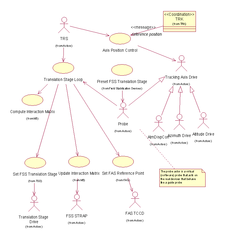
Class diagram:

Architecture:
A base Axis class defines the interface and the basic behaviour to
control a tracking axis drive. In particular it is defined a protocol
used by the trk package to pass to the tracking axis instances the
reference telescope altitude, azimuth, rotator angle and parallactic angle.
Every subclass has to convert properly this generic information into
encoder values for the specific axis.
There are therefore in principle five sub classes:
Future extensions foresee the following tracking axes:
- WaveFront Sensor support stage (from AO)
- Star Separator (from Dual Feed)
- Transversal Atmospheric Dispersion Compensator(Corrector)
The tracking axes are split in two categories
- Standard Axes
- Guide Probe Axes
The Standard Axes
For alitude and azimuth axis - being the main drives - the standard
approach using the VLT axis module is used.
For a detailed description of the axis module,
refer to the LCU Axis Control Module Design Description[RDV12].
The Guide Probe Axes
The Translation stage, FAS-Window and the M6 Interaction Matrix are
logically equivalent to the adapter guide probe of the UT. They have
to track a guide star.
The FSS translation stage has to calculate the proper (X,Y) for the
table in order to track the guide star, taking into account field
rotation and differential refraction with respect to the target object.
The FAS has to do the same in order to define the position of the
reference point used for auto guiding. This is due to the fact that
the TCCD used for field acquisition and auto guiding is fixed and NOT
mounted on a tracking guide probe.
Finally the Interaction Matrix is a function of azimuth.
Plate-scale Anisotropy Correction
The AT (and also the UT) will feature slight plate-scale anisotropy at the
Coudé (in the range 0.3%). Due to the high tracking accuracy required for
interferometry, this anisotropy has to be corrected when FSS needs to be
positioned in the Coudé Field-of View according to sky coordinates.
The anisotropy is due to the off-axis and cylindrical mirrors in the Coudé
Train. Therefore, the "principal axes" of this anisotropy rotates (w.r.t.
the fixed ground) together with the Fork (i.e. follows the Azimuth angle).
Since both FSS and FAS are on the same LCU and the calculation is
performed, with just a coordination transformation from (X,Y) table
coordinates to TCCD pixels, the same process is used.
When converting sky-coordinates into corresponding X-Y positions at the
Coudé Focus (and vice versa), the SW shall take into account the plate-scale
anisotropy.
A SW maintenance module shall enable to calibrate this anisotropy (TBC,
low priority, method TBD. In a first phase, the nominal values from optical
model will be used).
The AT Guide Probe
The AT guide probe software consists of several parts:
- Tracking software (trk)
- The tracking software is responsible for tracking the science object and providing all
data related to tracking a science object.
- Probe control software (probe)
- The probe control software is a generic approach to support the tracking of a guide star
relativ to a science object. It takes care of differential refraction and provides device
independent control data to control the specific devices like the translation stage or the
FAS window.
The software provides hooks for the device specific drivers
It also coordinates with the tracking software and provides the interfaces to it.
The major architecture is derived from the adapter/rotator software.
For a detailed description of the Adapter/Rotator LCU software,
refer to the Adapter-Rotator LCU Control Software Functional Specification
[RDV11].
The adapter/rotator software is refactored and the device independent parts are extracted.
- System specific probe control (atp)
- This software provides the base control of all probe devices in the AT system.
It can be called a super-probe that takes care of the coordination of
all individual probes
atp is the only interface between the probe control sofware and the individual
tracking devices.
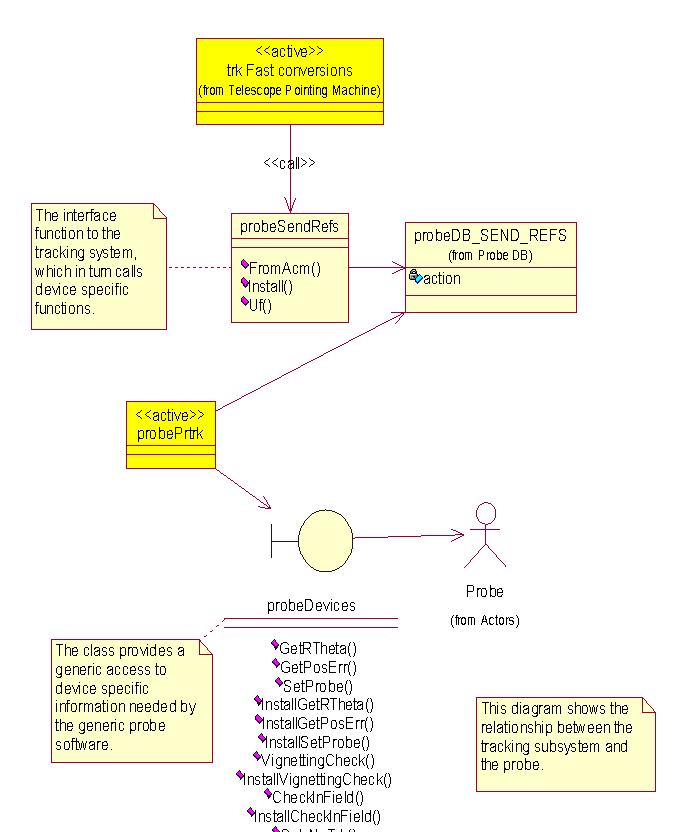
The diagrams below shows the major layout of the probe tracking system.
The first diagram shows the Use Case diagram of all use cases for the virtual probe.
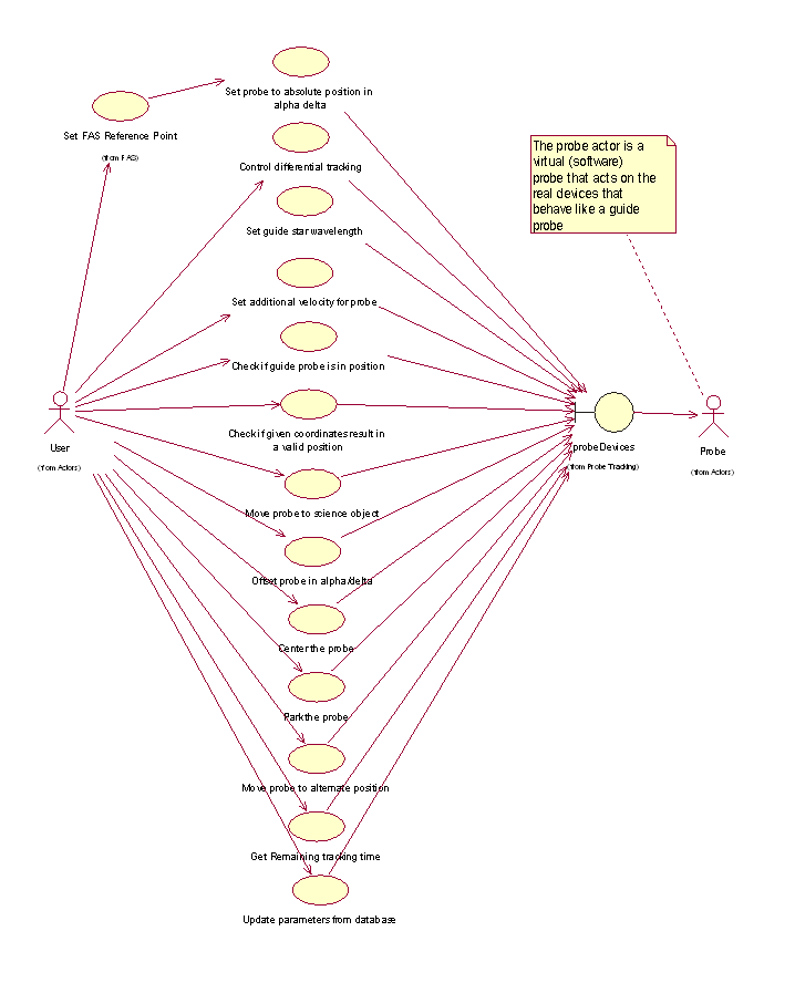
The following diagram lays out the main class diagram of the probe software,
that is based on lsf (LCU Server Framework).
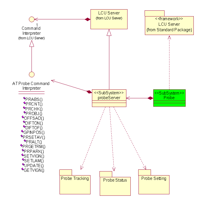
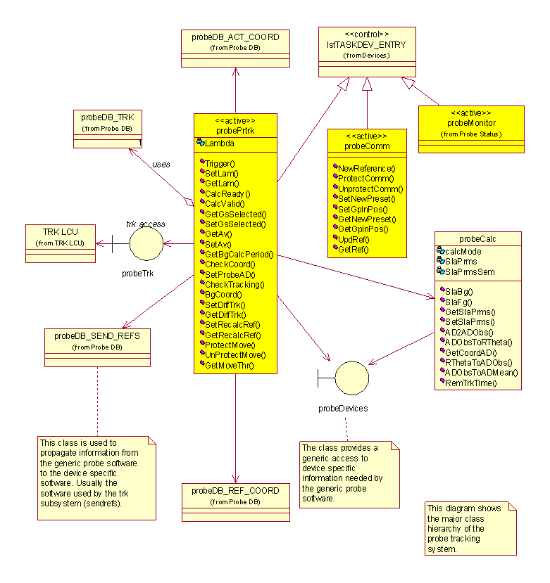
The next diagrams show the class layout of the probe tracking system.
The probePrtrk is a process that takes care of the astronomical
calculations relevant for the guide star (refraction, conversion mean
to observed, etc.).
The task is continously running and doing the astronomical calculations
for the guidestar with respect to the current science object.
The utility class probeCalc provides the main conversion
functions needed by the task.
The probePrtrk task supplies the tracking relevant data to the
probeSendRefs class that is the only interface to tracking. The SendRefs
function of this class is called by tracking and passes the actual
tracking data for the target object.
The probeDevices class provides the generic interface to the controlled
probe HW. It is responsible for all virtual guide probes.
The main probeDevices:SetProbe function calls a user function that should take
care of calling the device specific motion commands.
This function gets the tracking generated
setpoints (the setpoints of the target object) and the probe offset
w.r.t. current guide star. Each of them is implemented device
dependent, so that it can do the necessary transformations to the
device specific coordinate system.
It's the task of the specific classes to convert the data into
HW-dependent data and drive the respective HW-device.
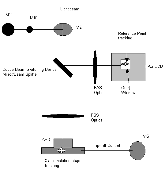
Compared with the guide probe arm of the UT we have several cases.
The Translation Stage Drive is a real guide probe, comparable with the
one of the UT. The XY-table moves in order to compensate for the tracking differences of
the target object and the guide star.
A big difference is the handling of the TCCD. Since the TCCD is fixed
we have to move the reference point of the TCCD that is used to do the
centroiding. In order to track the star properly the TCCD reference
point has to be updated on the fly.
The next drawing shows the optical path indicating what parts are moving.
The activity diagram below shows the flow of control from high to low level.
Activity diagram Guide star preset

The next two diagrams give the layout of the altitude main drive
servers. The architecture is identical to the UT.
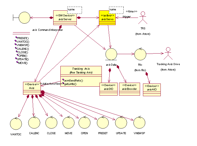
The details will be sorted out at package detailed design phase.
The Interfaces provided consist of:
- set of commands
- access library
tracking axis commands
The commands provide the interface on a very low level to operate,
tune and maintain the drive.
access library
The library consists of a set of functions in order to pass the
new reference positions.
Command Definition Table:
probeServer.cdt
axisServer.cdt
Reuse from VLT TCS: 90%
Code to handle the specific signals of the drive has to be produced.
All the code to handle the position loop, and all low level commands
can be reused. Eventually modification of control loops may be needed to
cope with friction.
The impact of the final design of the drives has also to be evaluated.
The newest VLT UT system provides also Software Tacho and Velocity
Control Loop. These should be usable also for ATs.
Issues to be Determined or
Resolved:
Since the calculation for the reference point on the tsd and the TCCD
is the same (just the scale and orientation is different) one can save
time in doing the calculation only once - for tsd - and then do just a
transformation to the TCCD coordinate system.
Last modified: Wed Oct 18 18:27:21 METDST 2000


