
|

|

|
|
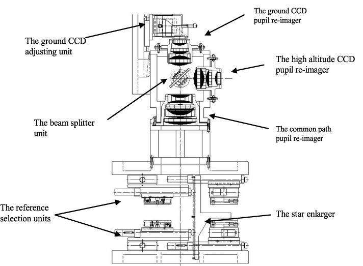
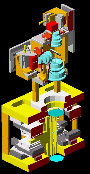
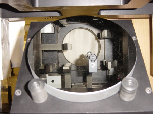
For practical reasons, the optical path is vertical. The LO WFS is
located above the MAD bench. A folding mirror redirects the incoming
light to SHS or to LO WFSs. The reference guide stars light coming
from the bottom of the box is caught by the star enlargers. The star
enlargers positioning is performed using two motorized linear stages
for each of them. Since the linear stages have to position
the star enlargers with a high precision, we decided to place all of
them horizontally.
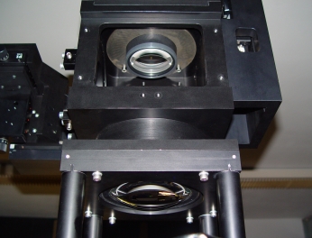
The pyramids placed at the top of the star enlargers split the image
into four parts. These 8 groups of 4 pupil images are first collimated
by the common-path pupil re-imager, then the light is divided by the
beam splitter between the ground and the high pupil re-imagers. These
second groups of lenses re-image the pupil on a plane conjugated to
the ground layer and to the high altitude layer. |
|
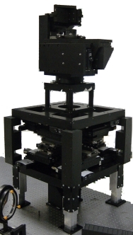
Since a few months the mechanical structure is in our laboratory. The
optics have also been delivered and the overall system is currently
being integrated in the laboratory.
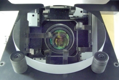
Each star enlarger is composed of two lenses and one prism. The two lenses increase separately the focal ratio for each star in order to reduce the pupil image for each star without changing the distance between the various stars across the covered FoV remains unchanged. The two lenses change the focal plane from an F/20 to F/300 while the pyramid purpose is to split the light into four pupils. The two lenses used for each star enlarger are custom ones, optimized to reduce chromatic effects. The second lens diameter fixes the minimum separation between two reference guide stars. The pyramid quality is essential for the wavefront measurement. Hence, the manufacturing has been done with particular specifications on the edge sharpness, the wedge of the back surface, the vertex angle repeatability and on the orthogonality of the faces. Due to the tight specification on the transmission an anti-reflection coating optimized for the full wavelength range has been done on each pyramid. The pin of the pyramid had to be centered with respect to the outer diameter with a precision of $\pm$0.1 mm. The surface flatness and roughness refer to the five faces of the pyramid. Since that several samples are required and due to the particular application for which these pyramids are used, the most important aspect is their similarity. The pupil superimposition on the ground layer detector is strongly related to both the global tilt of the star enlargers and the alignment of the three optical elements mounted on the star enlarger: the two achromatic lenses and the pyramid. A global tilt of the star enlarger translates into an approximately 1:1 angular shift of the exit pupil. When different stars enlargers are randomly tilted, the net effect is a blur of the pupil images, which translates into a wavefront measurement error. The alignment of the star enlarger components is a key issue. The two achromats alignment is also essential to avoid misalignment among different pupils: a relative decentering between the two achromats can affect the telecentricity of the system. The correct spacing between the two lenses is required otherwise the exit pupils corresponding to different stars enlargers are placed at different locations along the optical axis and the corresponding pupil images do not superimpose properly. The centering of the pyramid, instead, is a real issue only as long as the astrometric accuracy is of concern, since a decentering of the pyramid translates into a tip-tilt signal which might introduce a local warping of the corrected image astrometry. As long as the astrometry is not a scientific driver, like in the case of MAD, this point is not critical. The axial positioning is not critical, as the pyramid works in a F/300 beam with a very large depth of focus. The differential rotation among different pyramids might introduce mis-alignment errors among the different pupils. The requirement on this figure will be accomplished by the adjustment mechanism. The pyramids mounts allow to adjust the pyramids orientation, so that the beams from different pyramids are parallel, a necessary condition to ensure a proper pupil re-imaging. A rotation of a pyramid around its optical axis translates into a rotation of the four re-imaged pupils onto the detector plane. The re-imaging objective composed of two groups of 8 lenses is shown in Figure \ref{opticallayout}. It has a clear aperture of $d$~=~110~mm and a focal length $f$~=~115.7~mm. The design has been optimized in the full wavelength range 0.45~-~0.95 $\mu$m with uniform weighting. The equivalent FoV has been adjusted in order to match the CCD diagonal. The back-focal distance has been kept to the comfortable value of 20~mm. Furthermore the last lens is made by SILICA glass and the last surface is flat: this allows to account for the CCD window just by a simple modification of the thickness of this lens. Only standard Schott glasses (except SILICA) with high transmission in the wavelength range of interest have been selected. All the surfaces are spherical or plane; no cemented doublet or multiplet is present, in order to ensure high alignment precision. The objective is composed of two groups of lenses (O1 and O2): the first is a beam compressor, which reduces the beam cross section while collimating it; the second group focuses the beam at $F$/1.05 ratio. A convenient space of 125~mm is left between the two lens groups, allowing the insertion of the beam splitter for the ground and high altitude channels. The beam splitter is in a substantially collimated beam, hence it does not introduce any significant aberration. The optical quality of the pupil re-imager objective is practically diffraction limit. The lens groups forming the pupil re-imager have to be aligned in order to avoid a blur of the re-imaged pupil. The alignment tolerances have been computed for a maximum acceptable degradation of the RMS spot size of the order of 10$\%$: the relative decenter between the common path pupil re-imager and the ground or high altitude layer pupil re-imager should be adjusted with an accuracy better than $\pm 0.05$ mm, while the tilt of the lens groups with respect to the common optical axis should be smaller than $\pm 0.01^{\circ}$ for the common path and $\pm 0.15^{\circ}$ for the ground and the high altitude layer pupil re-imagers. In order to perform these adjustments, the lens groups mounts have been provided with adjusting mechanisms. Tip-tilt of each group of lenses is tune by using three screws with two different fine tuning. Three screws fixed at 120~degree translate each group by pushing it. |
|
|
|