If you are unsure about the quality of your calibration of these data in the last step, just use the provided files to continue by typing the following.
hds_close
get_data,'2002-02-15.cha'
HDS-file opened; mode=READ.
Scantable created.
% Compiled module: POLYFITW.
% Compiled module: STDEV.
GeoParms loaded.
GenConfig loaded.
Warning(DAT_FIND): component not found (FBAIRTEMPCONF)!
Warning(DAT_FIND): component not found (FBSOLIDTMPCONF)!
MetroConfig loaded.
% Compiled module: UNIQ.
StarTable created; number of entries = 11.
Finished reading catalogs.
Finished reading catalogs.
Number of new diameters added: 11.
Number of new (R-I) values found: 0.
Finished reading catalogs.
% Compiled module: POLY.
Finished astrometry computations.
Reference station set.
Scans loaded.
Finished visibility estimation.
Scan log read.
Observer log read.
CONSTRICTOR log read.
Before we begin with the image, we should look at the calibrated visibility data. We also will plot visibilities from a previously made model, even though a model is normally created after the image has shown which components to include in a model. To read the model file, do the following.
readmodel,'etavir.model'
Model file read and checked successfully.calcmodel
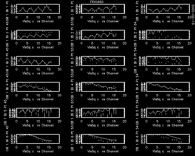
Now use the VisibilityPlot widget, as probably still displayed on your screen, to plot the calibrated visibility (VisSqC) versus channel for all channels, setting the slice to 'ch'. Also select the model plot option. You should then see the following for all baselines of the two spectrometers, if the range is set to [0,1.2] for the Y-axis, and [0,0] for the X-axis (Util|Range).


First of all, we can see that since the baselines of spectrometer 2, which are longer because they include W07, show a slower modulation of the visibility amplitudes than the shorter baselines of spectrometer 1, there are indeed two very different spacings present in the structure of this star.
We also notice that the calibration is not very good for these data. For now, there is nothing we can do about it since these data are very new and the calibration procedures need more work. Therefore, don't expect too high a quality image when we go about imaging these data!
Next, a very educational plot can now be made visualizing the visibility data in the aperture (or uv) plane. Use Calibrate|Stars to display the following widget.


Display the uv-coverage for all channels, baselines, and with the All-OBs option. Then use the command uvimage,/uv to display the model visibility amplitudes as an image underlying the uv-tracks. Notice the two different spacings of the fringe systems! The smaller spacing corresponds to the wide pair in this triple system, the wider spacing corresponds to the close pair.
