Fig. 1 - The UVES Control System Architecture
by Claudio Cumani and Robert Donaldson
European Southern Observatory
e-mail: ccumani@eso.org, rdonalds@eso.org
url: http://www.eso.org/~ccumani/,
http://www.eso.org/~rdonalds/
ABSTRACT
1) The ESO VLT Control System
The ESO Very Large Telescope (VLT) Control System is distributed
on different platforms:
All the computers are connected through Local Area Networks (LANs), and only standard components are used.
This applies also to all the Telescope Instruments, including those
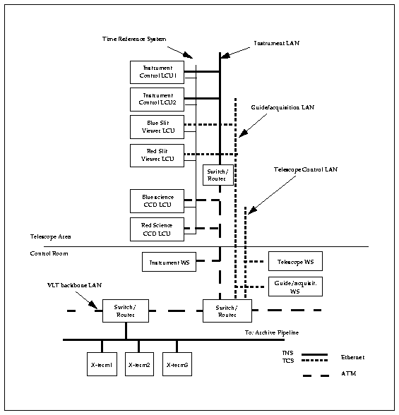
using CCD controllers. As an example, Fig. 1 presents an hypothesis for
the Control System architecture of the VLT high resolution spectrograph
called UVES (UltraViolet Echelle Spectrograph) is shown.

Fig. 1 - The UVES Control System Architecture
2) The ACE-LCU CCD Control System
Following the general architecture of the VLT Control System, the first
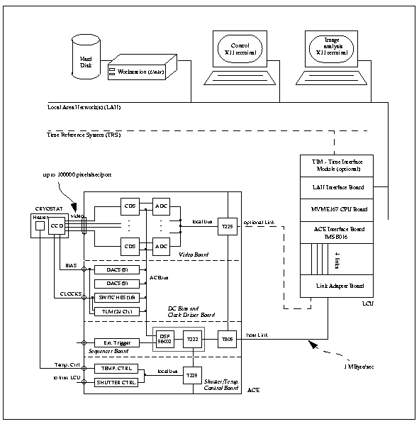
generation VLT CCD System is based on three platforms: workstation, LCU
and the Array Control Electronics (ACE), which is responsible
for clocking the CCD and processing and digitizing the video signal.
An overview of the system is shown in Fig. 2.

Fig. 2 - The ACE-LCU CCD Controller (Standalone System)
The CCD Controller LCU consists of:
The CCD Controller ACE consists of a network of four transputers (one T805, two T225, one T222) and a DSP (Motorola 56001) distributed on four printed circuit boards (Sequencer, Video, Clock/Bias and Shutter/Temperature Boards) and responsible for the synchronization of the readout operations, the data reorganization and transmission.
The CCD Controller Software has been written in C (workstation, LCU and ACE DSP) and occam (ACE transputers), and Tcl/Tk scripts are used within the Graphic User Interface (GUI) panels on the workstation. The VxWorks version of the driver for the IMS B016 Board has been developed at ESO.
The CCD Controller Software has the following characteristics :
The CCD Controller Software has the following functionalities :
A first prototype of this system was successfully tested in January
17-20, 1995, on the New technolgy Telescope (NTT) in La Silla (Chile).
In November, 1996, three operational ACE/LCU systems were installed at
the NTT, at the ESO Multi-Mode Instrument (EMMI) and the SUperb-Seeing
Imager (SUSI) instruments.
The following table shows the readout performances measured on the EMMI-Blue
Arm system (Tektronix 1124x1024 pixel full frame CCD), where the times
shown indicate the seconds between the starting of the readout of the CCD
and the end of the storage of the image on the workstation hardisk (in
FITS format).
| output(s) | used speed (*) | time (sec) |
| one | fast | 27.61 |
| two | fast | 17.37 |
| one | normal | 32.24 |
| two | normal | 19.64 |
| one | slow | 41.43 |
| two | slow | 24.27 |
(*)
fast = 2000 nsec for single slope of dual-slope correlated double
sampling (~73 kilopixel/sec/port)
normal = 4000 nsec for single slope of dual-slope correlated double
sampling (~56 kilopixel/sec/port)
slow = 8000 nsec for single slope of dual-slope correlated double
sampling (~39 kilopixel/sec/port)
3) The FIERA CCD Control System
In the recent years readout amplifiers for CCD devices have improved
so that it is now possible to attain low readout noise even with fast readout
speed (less than 2 electrons noise at 100 kpixel/sec/port and 4-6 electrons
noise at 1 Mpixel/sec/port). Today 1 MHz readout rate is adequate for acquisition,
focusing, flat-fielding, calibration, direct sky imaging, while the main
need for very low noise is for high resolution spectroscopy.
Today it is possible to build electronics that can run any CCD detector
or mosaic of detectors that we can envision for the next 10 years.
ESO must produce many CCD systems in the next few years in order to provide
for the VLT instruments and to upgrade the telescopes in La Silla (Chile).
Since the ACE-LCU system can not satisfy the readout requirements of
the new generation CCD devices (primarily due to the ACE-LCU communication
link, see Fig. 2), the most sensible approach for the ODT has been to produce
a new single "universal" controller that can optimally operate
all the scientific CCD chips or mosaics that ESO acquires for the next
10 years. Our philosophy is that the limitation of the entire detector
system should be due solely to the CCD and the imagination of the user.
This new advanced controller has been named FIERA (Fast Imager Electronic
Readout Assembly).
The Architecture of FIERA differs slightly from the standard VLT Architecture.
To achieve the readout requirements of the new generation CCD devices the
LCU was replaced with a SPARC CPU, connected to the CCD Electronics through
a 150 MBytes/sec full duplex optical fiber link. To avoid a major impact
on the VLT environment, the FIERA system software will keep - as far as
possible - the same interface to the VLT environment as the old CCD Controller.
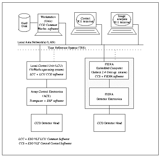
Therefore, FIERA should be able to replace the old controller in a clean
and transparent way, communicating with the Instrument Software running
on the workstation in the same way (see Fig. 3).

Fig. 3 - A comparison of the ACE and the FIERA systems in the VLT Architecture

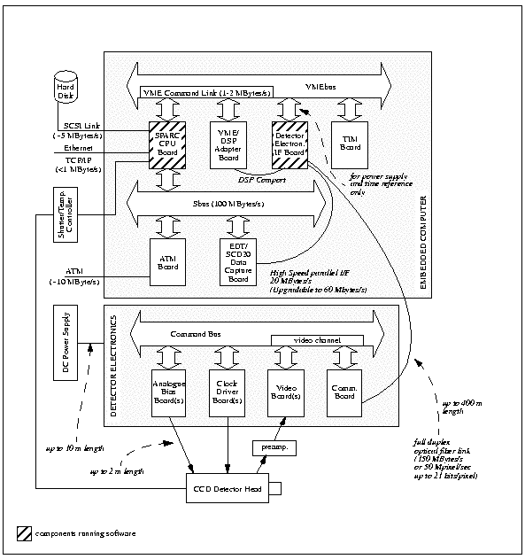
Fig. 4 - FIERA Hardware Architecture
The FIERA CCD Controller consists of two modules (see Fig. 4):
a) the Detector Electronics, consisting of
- a Communication Board, for the communications with the rest of the system,
- one or two Analogue Bias Boards,
- up to four Clock Driver Boards (12 clock lines/board),
- up to four Video Boards (4 channels/board)
b) the Embedded Computer, consisting of
- a SPARC CPU Board
- a Detector Electronics Interface Board (with two DSP TMS320C40), for
the communication with the Detector Electronics
- an EDT/SCD20 Data Capture Board, for fast data acquisition
- an ATM Board
- an ESO TIM Module (optional).
The Detector Electronics and the Embedded Computer are connected through
a 150 MBytes/sec full duplex optical fiber link (due to the transmission
protocol, the corresponding maximum video data rate is 50 Megapixels/sec,
for pixels up to 21 bits wide).
All the software runs on the SPARC CPU (Solaris Operating System, C
and C++ programming languages) and on the DSPs of the Detector Electronics
Interface Board (Parallel C). Analogue biases and high-current clock drivers
are fully programmable, with hardware limits on potentially damaging bias
voltages.
An "Oktoberfest '96" prototype of this system has been successfully
assembled in October 1996, in the Optical Detector Team laboratories at
ESO, Garching.
The following table shows the readout performances measured on a MIT/LL
420x420 pixel frame transfer CCD chip:
| output used | 1 |
| readout time | 0.20 seconds |
| readout speed | 880 kilopixels/sec/port |
| system noise | 1.3 electrons @ 1 megapixel/sec |
| crosstalk | negligible |
The system is still under test and redesign stage, but the general concept
and architecture have been proven.
The following goals are foreseen:
4) Acknowledgments
The authors would like to thank Antonio Longinotti and Philippe
Duhoux, of the ESO VLT Software Group, who helped in the preparation
of this article.
5) Bibliography
a) Beletic J., "The Plan for Optical Detectors at ESO",
The Messenger, n. 83, March 1996
b) Longinotti A., Cumani C., Duhoux P., "The VLT CCD Detectors
Control Software", The Messenger, n. 82, December 1995.
c) Reiss R., "ACE, Eso's next generation of CCD Controllers for
the VLT", in "Instrumentation in Astronomy VIII, 13-14 March
1994, Kona, Hawaii", SPIE Proceedings, vol. 2198
The following documents are available under anonymous ftp as compressed
postscript files:
d) VLT-SPE-ESO-17240-0227, 1.0, 08/04/93, CCD
SW Functional Specification
e) VLT-SPE-ESO-17240-0601, 1.0, 28/09/95, CCD
SW Design
f) VLT-SPE-ESO-13600-0568, 1.0, 08/12/95, ACE
SW Design
g) VLT-MAN-ESO-17240-0672, 1.4, 05/05/97, CCD
SW User Manual
h) VLT-MAN-ESO-17240-0917, 1.4, 05/05/97, CCD
SW User Manual for Standalone mode
i) VLT-SPE-ESO-13640-1266, 1.0, 16/04/97, FIERA
CCD Controller, Software Functional Specifications
Other information are available on the Optical
Detector Team web pages