|
|

EUROPEAN
SOUTHERN OBSERVATORY
Organisation Européenne pour des Recherches Astronomiques dans l'Hémisphère
Austral
Europäische Organisation für astronomische Forschung in der südlichen
Hemisphäre
VLT PROGRAMME
VERY
LARGE TELESCOPE
VLT
Software
---
VLT
Instrumentation Software Specification
Doc. No.: VLT-SPE-ESO-17212-0001
Issue: 5
Date: 30/09/2005
Name Date Signature
Prepared: A.Longinotti 30/09/2005
Name Date Signature
Approved: K.Wirenstrand
Name Date Signature
Released: M.Cullum
VLT PROGRAMME * TELEPHONE:
(089) 3 20 06-0 * FAX: (089) 3 20 06 514
CHANGE RECORD
|
ISSUE |
DATE |
SECTION/PAGE AFFECTED |
REASON/INITIATION DOCUMENTS/REMARKS |
|
1.0 |
All |
First issue |
|
|
2.0 |
|
All |
Changes to 1.0 are marked with change bars |
|
3 |
|
All 1.3 1.4 1.5 1.6 2.1, Figure 1 2.2, Figure 2 2.2.1 2.2.2 2.2.3 2.2.4 2.2.5 Chapters 3, 4, 5, 6, 7 3.8, 4.8 3.10 3.12, 4.18, 5.13 3.15, 4.21, 5.16, 6.5, 7.5 3.16, 4.22, 5.17 5.4 5.10 5.11 6.1 6.2 Chapter 7 Chapter 8 9.1.3 9.2 10.1 12.5 Chapter 13 Chapter 14 |
Whole document updated as from APR2004 INS sw status All requirements are tagged Updated list of applicable and reference documents Updated list of abbreviations and acronyms Changed definition of exposure. Added definition of Instrument mode Hardware architecture updated Software architecture updated. INS modules list and scope updated. Scope of Added INS configuration control Standards updated ICS, DCS, OS, MS, Definition of ICS, DCS simulation levels added Multiple ICSs supported Added test software as deliverable Added module names rules Remote control not supported Description of an exposure run updated Templates replace and enhance MOBS functionality Supervisory OS added for multi-instruments Instrument configuration updated Maintenance procedures as templates Scope of Added chapter on alarms Added description of User Station Programmatic interface updated Startup/Shutdown procedures updated Test Software as part of the deliverables New chapter on project management for instrumentation All requirements summarized in tabular form |
|
4 |
|
1.4 Chapter 10 |
Documents issue updated Added installation modules for different targets |
|
5 |
|
13.2.4 13.3.2 13.3.3 |
Document code during development Added Instrument Software Management Plan |
TABLE OF CONTENTS
TABLE
OF CONTENTS 3
1 INTRODUCTION 7
1.1 Purpose 7
1.2 Scope 7
1.3 Applicable Documents 7
1.4 Reference Documents 8
1.5 Abbreviations and Acronyms 9
1.6 Glossary 10
1.7 Stylistic Conventions 10
1.8 Naming Conventions 11
1.9 Problem Reporting/Change Request 11
2 OVERVIEW 12
2.1 Hardware architecture 12
2.1.1 Instrument LAN 12
2.2 Software architecture 13
2.2.1 INS Modules 14
2.2.2 INS Configuration Control 16
2.2.3 INS Environments 17
2.2.4 INS Users 17
2.2.5 INS Standards 17
3 INSTRUMENT CONTROL
SOFTWARE (ICS) 19
3.1 States 19
3.2 Commands 19
3.3 Parameters 19
3.4 FITS header keywords 19
3.5 Stand-alone mode 20
3.6 Logging 20
3.7 Safety 20
3.8 Simulation 20
3.9 Performance requirements 20
3.10 Multiple ICSs 21
3.11 Graphical User Interface 21
3.12 Test Software 21
3.13 Standards 21
3.14 Common Software 21
3.15 Modules naming conventions 21
3.16 Remote control 21
4 DETECTOR CONTROL
SOFTWARE (DCS) 22
4.1 States 22
4.2 Commands 22
4.3 Parameters 22
4.4 FITS header keywords 23
4.5 Stand-alone mode 23
4.6 Logging 23
4.7 Safety 23
4.8 Simulation 23
4.9 Performance requirements 24
4.10 Failure Mode Operation 24
4.11 Data transmission over instrument LAN 24
4.12 Data format 24
4.13 Real-Time Display 24
4.14 Disk space availability 24
4.15 Other requirements 24
4.16 Shutter control 25
4.17 Graphical User Interface 25
4.18 Test Software 25
4.19 Standards 25
4.20 Common Software 25
4.21 Modules naming conventions 25
4.22 Remote control 25
5 OBSERVATION SOFTWARE
(OS) 26
5.1 States 27
5.2 Commands 27
5.3 Parameters 27
5.4 Execution of exposures 27
5.5 Control of exposures 28
5.6 Changes during an exposure 28
5.7 Exposure Types 28
5.8 FITS header 28
5.9 Setup files 28
5.10 Templates 28
5.11 Supervisory OS (SOS) 29
5.12 Graphical User Interface 29
5.13 Test Software 29
5.14 Standards 29
5.15 Common Software 29
5.16 Modules naming conventions 29
5.17 Remote control 30
6 MAINTENANCE SOFTWARE
(MS) 31
6.1 Instrument Configuration 31
6.1.1 Privileges 31
6.1.2 Change Instrument Configuration Parameters 31
6.2 Maintenance and Verification procedures 31
6.3 Standards 31
6.4 Common Software 32
6.5 Modules naming conventions 32
7 OBSERVER SUPPORT
SOFTWARE (OSS) 33
7.1 Preparation of Observation Blocks 33
7.2 Exposure Time Calculator 33
7.3 Target selection 33
7.4 Standards 33
7.5 Modules naming conventions 33
8 ALARMS 34
9 INTERFACES 35
9.1 Graphical User Interface 35
9.1.1 General Guidelines 35
9.1.2 Performance Requirements 35
9.1.3 User Station 35
9.2 Programmatic Interface 35
9.2.1 Interface to Observation Handling tool
(P2PP) 35
9.2.2 Interface to on-line Archive 35
9.2.3 Interface to TCS 36
9.2.4 Interface to on-line data processing tools 36
10 INSTALLATION 37
10.1 Start-up / Shut-down 37
11 SYSTEM
ATTRIBUTES 38
11.1 Safety 38
11.2 Security 38
11.3 Availability 38
11.4 Maintainability 38
11.5 Adaptability and enhancement potential 39
11.6 Training 39
11.7 Documentation 39
12 DEVELOPMENT
AND TEST FACTORS 40
12.1 Design considerations 40
12.2 Implementation Considerations 40
12.3 Project control 40
12.4 Resource requirements 40
12.5 Test requirements 40
13 PROJECT
MANAGEMENT 41
13.1 General recommendations 41
13.2 Software life cycle 41
13.2.1 Requirements phase 41
13.2.2 Analysis phase 41
13.2.3 Design phase 42
13.2.4 Implementation phase 42
13.2.5 Integration phase 43
13.2.6 Assembly, Integration and Verification
phase 43
13.2.7 Commissioning phase 43
13.3 Project milestones 43
13.3.1 Preliminary Design Review (PDR) 43
13.3.2 Final Design Review (FDR) 44
13.3.3 Preliminary Acceptance Europe (PAE) 44
13.3.4 Provisional Acceptance Chile (PAC) 45
13.4 Product assurance 45
13.5 Change control 45
14 SUMMARY OF
REQUIREMENTS 46
The purpose of this document is to provide a basic software framework and to define software requirements which are applicable to any VLT/VLTI instrument. The document specifies:
- A standard and modular structure which is applicable to any VLT instrumentation software package.
- The common functionality of the standard software modules.
- The basic principles for user interaction and status display.
- The functional interfaces to the other parts of the VLT Software.
- Software which is common to all instrumentation software packages.
Additional software requirements, either derived from the Technical Specification or explicitly specified, will exist for each different VLT instrument. Based on the common requirements which are given in this document and on the instrument specific requirements, a Software Functional Specification shall be written for every different VLT instrument.
A detailed specification of the common instrumentation software is available in [AD 07], which complements and completes the information given here.
The interfaces to the Observation Handling Subsystem (P2PP) and on-line Archive are specified respectively in
[AD 06] and [AD 05].
This document follows logically [AD 02].
In order to trace more easily all requirements in the Software documents for specific instruments, in particular the Functional Specification, all requirements described here have a numbered tag: [INSnn].
The VLT instrumentation software concerns all VLT/VLTI instruments, which belong to the following categories:
Ø Cassegrain instruments (optical and infrared).
Ø Nasmyth foci instruments (optical and infrared).
Ø Coude’ instruments.
Ø Interferometric instruments.
The following documents, of the exact issue shown, form a part of this document to the extent specified herein. In the event of conflict between the documents referenced herein and the contents of this document, the contents of this document shall be considered as a superseding requirement.
|
Reference |
Document Number |
Issue |
Date |
Title |
|
GEN-SPE-ESO-19400-0794 |
3 |
|
DICB - Data Interface Control Document |
|
|
VLT-SPE-ESO-10000-0011 |
2 |
|
VLT Software Requirements Specification |
|
|
VLT-PRO-ESO-10000-0228 |
1 |
|
VLT Software Programming Standards |
|
|
VLT-PLA-ESO-10000-0441 |
1.0 |
|
VLT Science Operation Plan |
|
|
VLT-ICD-ESO-17240-19400 |
2.6 |
|
ICD between VCS and Archive |
|
|
VLT-ICD-ESO-17240-19200 |
1.3 |
|
ICD between VCS and OH |
|
|
VLT-SPE-ESO-17240-0385 |
4 |
|
INS Common Software Specification |
|
|
VLT-MAN-ESO-17210-0667 |
1.2 |
|
Guidelines for VLT applications. |
|
|
VLT-PLA-ESO-00000-0006 |
2 |
|
VLT Software Management Plan |
|
|
VLT-ICD-ESO-15410-2117 |
2.3 |
|
ICD between VLTI ISS and Instrumentation Sw |
The following documents are referenced in this document.
|
Reference |
Document Number |
Issue |
Date |
Title |
|
VLT-MAN-ESO-17200-0888 |
1.0 |
|
VLT Common Software Overview |
|
|
VLT-MAN-ESO-17200-0642 |
4 |
|
VLT Common Software Installation Manual |
|
|
VLT-SPE-ESO-17100-3439 |
1 |
|
Paranal Network/Computers Design Description |
|
|
VLT-MAN-SBI-17210-0001 |
3.7 |
|
LCU Common Software User Manual |
|
|
VLT-MAN-ESO-17210-0600 |
1.7 |
|
Motor Control sw User Manual API/ACI |
|
|
VLT-MAN-ESO-17210-0669 |
1.6 |
|
Motor Engineering Interface User Manual |
|
|
VLT-MAN-ESO-17210-0619 |
2.4 |
|
Central Control Software User Manual |
|
|
VLT-MAN-ESO-17210-0707 |
1.6 |
|
On Line Database Loader User Manual |
|
|
VLT-MAN-ESO-17210-0771 |
1.8 |
|
EVH User Manual |
|
|
VLT-MAN-ESO-17210-0770 |
1.8 |
|
Extended CCS User Manual |
|
|
VLT-MAN-ESO-17210-0690 |
5 |
|
Panel Editor User Manual |
|
|
VLT-MAN-ESO-17240-0853 |
3 |
|
INS Common sw - oslx User Manual |
|
|
VLT-MAN-ESO-17240-0672 |
1.6 |
|
CCD Detectors Control Software User Manual |
|
|
VLT-MAN-ESO-13640-1388 |
3 |
|
FIERA Control Software User Manual |
|
|
VLT-MAN-ESO-14100-1878 |
1.4 |
|
IRACE-DCS User Manual |
|
|
VLT-MAN-ESO-17240-0934 |
5 |
|
INS Common sw - Base ICS User Manual |
|
|
VLT-MAN-ESO-17240-2265 |
4 |
|
INS Common sw - Base OS Stub User Manual |
|
|
VLT-MAN-ESO-17240-1913 |
4 |
|
Installation Tool for VLT Sw packages |
|
|
VLT-MAN-ESO-17240-2153 |
4 |
|
INS Common sw - Startup Tool User Manual |
|
|
VLT-MAN-ESO-17220-0737 |
3 |
|
HOS/Sequencer User Manual |
|
|
P.Ward, S.Mellor, Yourdon Press, |
|
1985 |
Structured Development for Real-Time Systems |
|
|
J. Rumbaugh et. al., Prentice Hall, |
|
1991 |
Object-Oriented Modeling and Design |
|
|
VLT-MAN-ESO-17220-1332 |
4 |
|
HOS/Broker for Observation Blocks User Manual |
|
|
VLT-MAN-ESO-17240-2240 |
4 |
|
INS Common sw for Templates User Manual |
|
|
VLT-MAN-ESO-17240-2325 |
4 |
|
INS Common sw Configuration tool User Manual |
|
|
VLT-MAN-ESO-17240-2606 |
3 |
|
Base ICS GUI User Manual |
|
|
VLT-MAN-ESO-19200-1644 |
3 |
|
Phase 2 Proposal Preparation Tool User Manual |
|
|
VLT-SPE-ESO-19000-1618 |
1 |
|
Data Flow for VLT instruments Requirements |
|
|
VLT-PLA-ESO-17240-2266 |
5 |
|
INS Acceptance Test Plan Template Document |
|
|
VLT-MAN-ESO-17240-1973 |
5 |
|
Template Instrument User and Maint.Manual |
|
|
VLT-MAN-ESO-17200-0780 |
2 |
|
Configuration Management Module User Manual |
|
|
VLT-MAN-ESO-17240-0637 |
3 |
|
INS Common sw – dxf User Manual |
|
|
VLT-MAN-ESO-17240-0866 |
2.8 |
|
INS Common sw – rtd User Manual |
|
|
VLT-MAN-ESO-17240-0880 |
2 |
|
INS Common sw – ist User Manual |
|
|
VLT-MAN-ESO-17240-3153 |
1 |
|
STRAP Instrument WS software User Manual |
|
|
VLT-MAN-ESO-17230-0942 |
2 |
|
TCS User Manual |
|
|
VLT-MAN-ESO-17240-0725 |
1.3 |
|
INS Common sw – pco User Manual |
|
|
VLT-SPE-ESO-17240-3221 |
1 |
|
Template for Instrument Sw Requirements Specs |
|
|
VLT-SPE-ESO-17240-3222 |
2 |
|
Template for Instrument Sw Functional Specs |
|
|
VLT-SPE-ESO-17240-3223 |
1 |
|
Template for Instrument Sw Detailed Design |
|
|
VLT-TRE-ESO-17240-3162 |
2 |
|
Template for Instrument Software PAE Report |
|
|
VLT-MAN-ESO-17200-0981 |
2 |
|
VLT Problem Report Change Request User |
|
|
VLT-MAN-ESO-17000-2972 |
1 |
|
VLT SW Basic Tools and Working Environment Guidelines |
|
|
VLT-PLA-ESO-17240-3786 |
1 |
|
Template for Instrument Software Management Plan |
1.5 Abbreviations and Acronyms
This document employs several abbreviations and acronyms to refer concisely to an item, after it has been introduced. The following list is aimed to help the reader in recalling the extended meaning of each short expression:
|
ADC |
Analogue to Digital Converter |
|
AIV |
Assembly, Integration and Verification |
|
API |
Application Programmatic Interface |
|
ATM |
Asynchronous Transfer Mode |
|
ATP |
Acceptance Test Plan |
|
BOB |
Broker for Observation Blocks |
|
CCD |
Charge Coupled Device |
|
CCS |
Central Control Software |
|
CPU |
Central Processing Unit |
|
DCS |
Detector Control Software |
|
DFE |
Detector Front-End Electronics |
|
DICB |
ESO Data Interface Control Board |
|
DMA |
Direct Memory Access |
|
DRS |
Data Reduction Software |
|
DSP |
Digital Signal Processor |
|
FDR |
Final Design Review |
|
FITS |
Flexible Image Transport Format |
|
GUI |
Graphical User Interface |
|
HW |
Hardware |
|
HOS |
High Level Operating Software |
|
ICS |
Instrument Control Software |
|
INS |
Instrumentation Software |
|
I/O |
Input/output |
|
ISDD |
Instrument Software Design Description |
|
ISFS |
Instrument Software Functional Specification |
|
ISURS |
Instrument Software User Requirements Specification |
|
ISUM |
Instrument Software User Manual |
|
ISMM |
Instrument Software Maintenance Manual |
|
IWS |
Instrument Workstation |
|
LAN |
Local Area Network |
|
LCC |
LCU Common Software |
|
LCU |
Local Control Unit |
|
MIDAS |
ESO-Munich Image Data Analysis System, ESO-MIDAS TM |
|
MOBS |
Multiple Observation Software |
|
MS |
Maintenance Software |
|
N/A |
Not Applicable |
|
|
Observation Block |
|
OBD |
Observation Block descriptor |
|
OLAS |
On-Line Archive Subsystem |
|
OLDB |
On-Line DataBase |
|
OMT |
Object Modeling Technique |
|
OO |
Object Oriented |
|
OS |
Observation Software |
|
|
Observer Support Software |
|
PAE |
Preliminary Acceptance |
|
PAF |
Parameters File |
|
PDR |
Preliminary Design Review |
|
RAM |
Random Access Memory |
|
SOS |
Supervisory Observation Software |
|
STRAP |
System for Tip-tilt Removal with Avalanche Photodiodes |
|
SW |
Software |
|
TBC |
To Be Clarified |
|
TBD |
To Be Defined |
|
TCCD |
Technical CCD |
|
TCS |
Telescope Control Software |
|
TIM |
Time Interface Module |
|
TRS |
Time Reference System |
|
TSF |
Template Signature File |
|
UIF |
(Portable) User Interface (Toolkit) |
|
UNIX |
Trademark of Bell Laboratories (operating system) |
|
VCSOLAC |
VLT Control Software On-Line Archive Client |
|
VLT |
Very Large Telescope |
|
VME |
Versa Module Eurocard |
|
VOLAC |
VLT On-Line Archive Client |
|
WS |
Workstation |
Ø Detector Front-End Electronics (DFE)
It is the electronics located near the detector and normally galvanically isolated from the instrument. It consists of, for example, ADCs, programmable detector and clock voltages, clock pattern generation, fiber optic links to the LCU, etc. Processing units (e.g. DSPs) control the electronics and provide for data transmission and communication with the detector LCU.
Synonym for DFE is: "detector controller".
Ø Exposure[1]
It encompasses the setup of the instrument, one or more integrations, followed by the readout of at least one detector and the storage of the obtained data frame(s) in a FITS file and/or in memory for display.
Ø Instrument mode
It defines the basic instrument setup for a specific observing mode e.g imaging or spectroscopy. It is selected through the keyword INS.MODE.
Ø Instrument workstation IWS
It is the workstation which is assigned to control instrument and/or detector LCUs.
Ø Integration
It is the time interval for which a detector is collecting data. The integration is a subunit of an exposure and does not imply a readout operation.
Ø On-line MIDAS
It is the MIDAS session which runs in background, parallel to the foreground MIDAS. The on-line MIDAS executes commands given by on-line processes whereas the foreground MIDAS is used for interactive work.
Synonyms for it are: "background MIDAS", "parallel MIDAS".
Terms like Observation block, Template, Template Signature File are defined in [AD 06].
Terms like Setup file, Short Hierarchical Format are defined in [AD 07].
The following styles are used:
bold
in the text, for commands, filenames, pre/suffixes as they have to be typed.
italic
in the text, for parts that have to be substituted with the real content before typing.
teletype
for examples.
<name>
in the examples, for parts that have to be substituted with the real content before typing.
bold and italic are also used to highlight words.
This implementation follows the naming conventions as outlined in [AD 03].
1.9 Problem Reporting/Change Request
The form described in [RD 42] shall be used.
Each instrument is characterized by an identifier (or ID) and a prefix.
The Instrument ID is normally set to the name of the instrument (uppercase). Example: UVES.
The Instrument prefix is a two characters string, used e.g. to identify the nodes in the Instrument LAN, files and processes. Example: uv (for UVES).
The very first step in the design of a new Instrument is to define its ID and prefix in agreement with ESO [INS01].
The VLT has a distributed control system consisting of a large number of Local Control Units (LCUs) and Workstations (WSs) connected to each other via Local Area Networks (LANs). A complete overview of the VLT network concept is given in [RD 03].
Figure 1 shows an example for one instrument on a VLT unit telescope.
The instrument hardware (devices and detector camera head and front-end electronics) is located in the Telescope Area. The Instrument LCUs (two in the example) control all devices, except the detector.
The detector is controlled by a dedicated Detector LCU (in the current architecture of VLT standard scientific detector controllers the standard VME-based LCU is replaced with an Ultra-Sparc WS).
Control and data information is transferred over the Instrument LAN between the Instrument Workstation and the Instrument and Detectors LCUs.
The Instrument
Workstation (IWS) is located in the Computer Room in the
Time critical synchronization between LCUs is achieved via the Time Reference System [INS02].
Each IWS is statically assigned to an instrument and directly connected to the instrument LAN. The Instrumentation Software on the IWS and LCUs usually remain always active, i.e. during day and night time, also when it is currently not used for observations. During this time it monitors the hardware status of the instrument, performs test procedures when requested by operations staff, etc.
Instruments are normally in an operational, also called on-line, or stand-by mode.
A number of screens of the User Station in the central control room are dedicated to the instrument control. Normally the two screens of the User Station console are used: one for control and status display and the other one for real-time image display.
Every instrument has its own dedicated LAN so that the full bandwidth of the LAN is available for the instrument. The LAN traffic from other instruments and systems is filtered by a router.
For test and maintenance work close to the instrument it is possible to connect X-terminals or a mobile user station directly to the instrument LAN.
The Instrument LCUs and the technical CCD LCUs, if any, have a normal Ethernet connection to the Instrument LAN.
Scientific detectors LCUs, as well as the Instrument WS, have a large bandwidth connection (at present ATM) to the Instrument LAN.
The naming conventions for the Instrument LAN nodes are described in [RD 03]. In particular, all node names must be maximum 7 characters long. Additional rules are imposed by the INS Common Software [INS03]:
- The IWS node name must begin with w<prefix>. If the first two letters of the Instrument ID correspond to the prefix, the IWS node name it is set to w<ID> (lowercase).
Example: wuves (UVES IWS).
- The Instrument LCUs node name must be l<prefix>ics<index>. The index always starts from 1
Examples:
luvics1, luvics2 (UVES Instrument LCU
1 and 2).
- For
scientific detectors the LCU node name must begin with w<prefix>.
Examples: wuvccdr, wuvccdb (Ultra-Sparc WSs for UVES CCD red and blue arm).
- For
all the other LCUs (e.g. technical CCD LCUs), the node name must begin with l<prefix>
Example:
luvsvr, luvsvb (UVES slit viewer red
and blue arm).
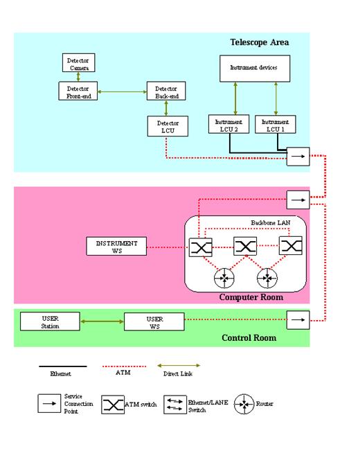
Figure 1 Hardware architecture
Figure 2 shows the standard architecture of an Instrumentation Software and the data flow between its components.
Observation Blocks (OBs) are normally prepared by the observing team at the home institute well before the observing night, using the Phase 2 Proposal Preparation (P2PP) Tool (see [RD 27]).
During the
observing run, the next
BOB reads the
contents of the
The typical simple sequence of commands sent to OS by science observation templates to execute an exposure is:
- SETUP (one or more)
- START (exposure)
- WAIT (till exposure finished)
As a result of an exposure, DCS generates detector data and saves them in a FITS file. The OS process responsible for archiving data takes care of merging into that file the information, coming from the other sub-systems (TCS and ICS), related to the same exposure. It then informs the standard VLT On-Line Archive (VOLAC) process that a new file is ready to be archived. In turn, VOLAC passes this information to the standard VCSOLAC process, which finally transfers the file to the On-Line Archive Subsystem (OLAS) on the On-Line Archive WS.
An instrumentation software package is subdivided into the following standard INS software modules,[2] [INS04]:
- Instrument Control Software (ICS)
- Detector Control Software (DCS)
- Observation Software (OS)
- Maintenance Software (MS)
- Observer
Support Software (
The Instrument Control Software (ICS) controls all devices which belong to the instrument, except the detectors.
ESO provides standard software, called Base ICS (ICB). See [RD 16] and [RD 26] for more details.
The Detector Control Software (DCS) carries out all tasks to control the detector sub-system, to perform real-time image processing, if and when needed, and to transfer detector data to the workstation.
ESO provides software for the standard scientific infrared detector system (IRACE, see [RD 15]), for the standard scientific optical detector system (FIERA, see [RD 14]) and for the standard technical CCD system (TCCD, see [RD 13]).
The Observation Software (OS) is used to coordinate the execution of an exposure for a given observing mode.
It provides for setup and coordination of the various control systems such as instrument, detector, telescope and also interfaces to other software like the Archive system to archive observation data.
It also completes the final FITS header for the observation data file.
The OS does not access hardware functions of the instrument. It has the "knowledge" of how to coordinate the control systems to perform exposures for given observing modes.
The OS Server, shown in Figure 2, executes single exposures. Sequences of exposures are instead executed by templates.
Acquisition, calibration and science templates (signature files and scripts), needed to build the Instrument Package, required by P2PP, are also part of OS. See [AD 06] and [RD 23] for more information on templates.
An Instrument may provide the so called generic template, which is the basis for the Multiple Observation Software (MOBS) [3]. See [RD 23] for more information on MOBS and generic templates.
ESO provides standard software: BOSS (see [RD 17]) for OS Server and Archiver and TPL (see [RD 24]) for templates.
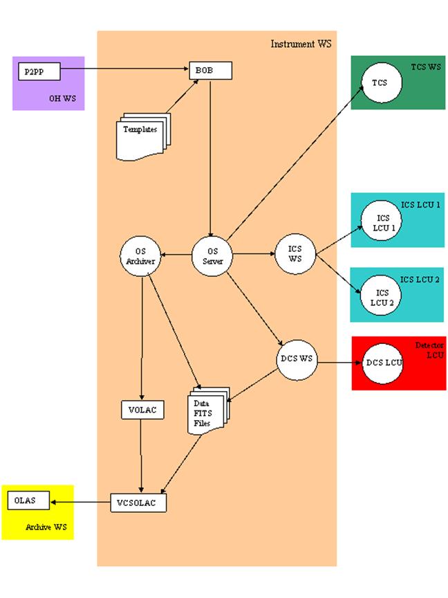
Figure 2 Software architecture
The Maintenance Software (MS) is used for instrument configuration, check-out and troubleshooting. It also provides technical templates, e.g to verify the instrument calibration, which involves the instrument and detector LCU.
ESO provides standard software for Instrument configuration (CTOO, see [RD 25]).
The Observer Support Software (OSS) consists of tools to support the observer in the preparation of an observing run, such as a GUI for the preparation of Observation Blocks (OB) and an exposure time calculator. For the majority of the instruments, standard tools are provided by ESO (e.g. P2PP for the OBs preparation), and no additional instrument specific software needs to be implemented.
The INS package must also contain facilities to build, install and startup/shutdown the Instrumentation Software [INS05].
ESO provides standard software for installation (PKGIN, see [RD 18]) and startup/shutdown (STOO, see [RD 19]).
The data reduction is performed by the pipeline Software on a dedicated WS (see [RD 28]). The description of this Software is outside the scope of the present document. It is important to stress that the results of the pipeline data processing are not available on the IWS. Whenever the Instrumentation Software (INS) on the IWS needs to know the results of data processing, e.g. to decide what to do next, and cannot accept that this decision is taken by the operator after checking the pipeline results on a dedicated separate screen, then that kind of data processing must be performed within INS. If there are no real-time requirements, the data processing required by INS should be implemented within the templates [INS06]. The ESO standard library for templates (see [RD 24]) provides an interface to the standard image processing tool (at present on-line MIDAS).
If and which data processing must be implemented within INS has to be discussed at the Instruments Design Reviews and must be subject to prior ESO approval [INS07].
The usage of a tool different to the current standard is also subject to prior ESO approval [INS08].
Users interact with the INS via the VLT Graphical User Interface (GUI). All User Interfaces at the VLT have a common "look and feel". Specific VLT panels shall be developed for every instrument, based on the VLT GUIs Editor (see [RD 11]) [INS09].
Last but not least, the INS package must include also test Software for each of the INS modules [INS10]. The minimum set of tests, which must pass for the Preliminary Acceptance Europe, is defined in [RD 29].
ESO provides the code for a Template Instrument (see [RD 30]). It should be used as starting point for building a new instrument from scratch [INS11]. It includes also examples of test scripts and automatic regression test procedures.
2.2.2 INS Configuration Control
It must be possible to rebuild the Instrumentation Software from scratch. In order to achieve this purpose, all files belonging to the INS package must be managed using the VLT standard tool for configuration management cmm (see [RD 31]). This tool provides, among others, the archiving functionality for the VLT Software.
The usage of cmm is mandatory and requires that files are grouped into VLT Software modules (see definition in [AD 03]) [INS12]. Note that the concept of VLT Software modules and INS modules, as described in section 2.2.1, are different. In general every INS module consists of several VLT Software modules.
The general rule for all instrumentation cmm modules is that their name should be built according to the following scheme [INS13]:
<prefix><INS
module id>[<description>]
where
prefix = two characters Instrument prefix
INS module id = one letter code for the INS module it belongs to:
i for ICS
d for DCS
o for OS
m for MS
s for
description = string (up to three letters) identifying the role of the module. The description part is normally omitted only for the main VLT Sw module of a specific INS module.
Examples:
uvi = main ICS module for UVES
uvipan = panels for UVES ICS
vnd[4] = main DCS module for VINCI
vndacq = data acquisition module for VINCI DCS
uvo = main OS module for UVES
uvopan = panels for UVES OS
The only exception to this rule are the instrument package installation module, called <prefix>ins (example: uvins for UVES) and the module containing all instrument dictionaries, called dic<ID> (example: dicUVES for UVES)[5].
All rules defined in [AD 03] apply also to the INS package [INS14]. In particular, the name of all files and global variables contained and defined in a Software module must begin with the module name.
Also the Instrument configuration parameters must be kept under configuration control [INS15]. ESO provides a tool for INS configuration management (ctoo, see [RD 25]). All files defining the Instrument configuration must belong to the same Software module; this module belongs to the INS Maintenance Software (MS) [INS16].
See also [RD 30] for an example of how to deal with changes in the Instrument configuration.
2.2.3 INS Environments
The Instrumentation Software, as any other VLT Software package, runs in CCS environments. There is one CCS environment defined for each node in the Instrument LAN[6] [INS17].
All WS CCS environments must be of type CCS-lite (full-CCS is not supported any more) [INS18].
The name of the CCS environment must be the same as the name of the corresponding LAN node (see section 2.1.1) [INS19].
Example:
· wuves. UVES IWS CCS-lite environment (see environment variable RTAPENV)
· luvics1. UVES ICS LCU1 LCC environment.
· luvics2. UVES ICS LCU2 LCC environment.
· luvsvr. UVES read arm slit viewer TCCD LCC environment.
· luvsvb. UVES blue arm slit viewer TCCD LCC environment.
· wuvccdr. UVES read arm scientific CCD CCS environment
· wuvccdb. UVES blue arm scientific CCD CCS environment
· wuvtcs[7]. TCS simulation CCS environment for UVES (see environment variable TCS_ENVNAME)
Every instrument defines two user names, which must be known on all nodes in Instrument LAN [INS20]:
- The INS manager, responsible for building and installing the Software. The name must be <ID>mgr (all lowercase).
Example: uvesmgr
- The INS runtime user, responsible for starting/stopping and running the INS environments and the INS Software. The name must be <ID> (all lowercase).
Example:
uves
It is recommended to get used to the repartition of responsibilities between the two users already from the beginning of the development.
The INS package must be based on the standard packages distributed with VLT Software releases. In particular:
· TCCD DCS is based on the CCD Software (see [RD 13]) [INS21].
· Infrared scientific DCS is based on the IRACE Software (see [RD 15]) [INS22].
· Optical scientific DCS is based on the FIERA Software (see [RD 14]) [INS23].
· Transfer of detector data is based on the dxf package (see [RD 32]) [INS24].
· The display of detector data is based on the rtd package (see [RD 33]) [INS25].
· ICS is based on the icb package (see [RD 16] and [RD 26]) [INS26].
· OS is based on the boss package (see [RD 17]) [INS27].
· Templates are based on the tpl package (see [RD 24]) [INS28].
· The handling of FITS keywords and files is based on the oslx package (see [RD 12]) [INS29].
· The Instrument Software installation is based on the pkgin package ([RD 18]) [INS30].
· The Instrument Configuration is based on the ctoo package (see [RD 25]) [INS31].
· The Instrument Software Start-up/Shutdown is based on the stoo package (see [RD 19]) [INS32].
3 INSTRUMENT CONTROL SOFTWARE (ICS)
The Instrument Control Software (ICS) shall control all devices belonging to an instrument, except the detectors [INS33]. Examples for instrument devices are: slit, grating, flip mirror, filter wheel, lens wheel, temperature sensors, pressure sensors, calibration lamps, etc.
ICS in general consists of one part, which runs on LCU(s) and one part, which runs on the IWS.
The LCU part is responsible for the interface to the devices hardware and in general the low-level control, including real-time functionality, if any.
The WS part is responsible for the coordination between LCUs, if more then one, their simulation, if not available (e.g. in a development or test environment) and for the API to OS.
All the standard ICS states [INS34], and the commands to change state, are specified in [AD 07].
All the standard ICS commands [INS35], the command syntax and conventions are specified in [AD 07].
The ICS LCU software maintains all its parameters in a local database.
ICS parameters can be grouped into the following categories:
- Configuration parameters (see also section 6.1)
- Setup parameters (set values, see point 3 below)
- Status parameters (actual values, see point 3 below)
The following rules are mandatory:
- All parameters values (e.g. wavelength range, operating modes, wanted device position, current device position etc.) shall be stored into the local database. They shall never be hard-coded in the Software [INS36].
- The complete status of the instrument-LCU shall be stored into the local database in order to enable the WS Software to monitor the status of the LCU. This implies that the local database is updated when the hardware status is read or the software status changes [INS37].
- Parameters set by a command, like position for a motor, shall not be modified by the LCU software until a new command to change the value of this parameter is received. This is called the set value of the parameter. Parallel to the set value there shall be a value for the real status which is called the actual value of the parameter [INS38].
- Set and actual value of a parameter must be stored in separate attributes in the local database [INS39].
- For actions like moving a motor, setting a temperature etc., there shall be a status parameter indicating that the action is going on or was completed or failed [INS40].
- Set values shall be checked for validity (e.g. known filter name or slit width in the allowed range) [INS41].
- Set parameters and values shall be checked against the associated dictionary for syntax validity (see [AD 01] and [RD 12] for more information on dictionaries) [INS42].
- Many parameters from the LCU local database (status, setup, configuration, etc.) must be copied to the on-line database on the workstation, so that they are directly accessible by other programs on the workstation. For example, the User Interface reads from the on-line database status information, which is to be displayed.
The copying shall be done automatically with the CCS Scan system (see [RD 07]) and needs to be configured, as part of the INS build and installation procedure (see [RD 18]) [INS43]. For each parameter one must specify:
- if it is to be copied cyclically
- if it is to be copied on change of
value. The Scan system provides for a dead-banding option. Dead-banding option means that when the
value of a parameter changes by more than a specified amount then it is
copied.
- The ICS FITS header part must contain [INS44]:
- The actual status of the instrument, which can be obtained with the standard command (see [AD 07])
STATUS –header [-dumpFits <filename>].
It must be ensured that the FITS header data contain the updated status.
- Statistics (e.g median, r.m.s.) on parameter values which can change during an exposure (e.g instrument temperature, pressure, etc.).
- The ICS shall be able to produce FITS header data in simulation (test) mode, i.e. when the LCU is not available or when the hardware of some devices connected to the LCU is simulated. Simulation must be clearly stated in the FITS header [INS45].
- Keywords appearing in the FITS header must comply with the rules described in [AD 01] and shall be checked against the associated dictionary for syntax validity (see [AD 01] and [RD 12] for more information on dictionaries) [INS46].
The stand-alone mode is used:
- To enable Operations staff to test and access the individual devices of the instrument without starting the other modules of the INS package. This requires a dedicated GUI panel with a detailed status display (see also [RD 26]) [INS47].
- To test (debug) the LCU application Software without necessarily involving other modules of the INS package.
The mechanism for logging is specified in [RD 04] and [RD 07] and the general contents and format for Archive in [AD 01].
Moreover, a number of other data and events must be logged [INS48]:
- Pressure and temperature values, e.g when they change by a certain amount when the instrument is in operation or stand-by mode.
- Any change of the instrument setup (e.g. a motor movement, a lamp turning on). For continuous movements (e.g. derotator tracking), only the start and end of the action shall be logged.
- Any instrument setup error.
- Any automatic device movement during an exposure (focus correction due to temperature change).
- Booting LCUs shall be logged.
Note however that, especially for logs produced by LCUs, too many logs risk to overload the logging system. As a rule of thumb, it should be avoided to generate periodical logs (e.g. change of temperature) at frequencies higher than 0.1 Hz. If samples collected at higher frequency need to be logged, they should be better grouped into one single log (or, if acceptable, only their average value is logged).
Safety requirements are specified in [RD 04].
- Two levels of simulation shall be implemented:
- Simulation for the entire instrument LCU at workstation level. This level is used e.g. to test other Software, like OS, when no instrument LCU is available or connected to the instrument LAN. At this level, it is not necessarily required to provide for a full "instrument simulator". In simple cases it may be just sufficient to store the set value into the on-line database, e.g after the command “SETUP –function INS.FILT1.NAME H” the value H is stored into the on-line database [INS49].
- Simulation for some device hardware at LCU level. This level is used e.g. when the hardware associated to one or more devices is not available or broken. This level of simulation is achieved in that the LCU application Software skips all actions towards the hardware interface for those devices and assumes that the hardware behaves as expected [INS50].
- Simulation, at whatever level, must be repeatedly indicated to the user. There shall be no "hidden" simulation which can corrupt a real observation [INS51].
- Devices
which are simulated must be clearly stated in the FITS header [INS52].
General performance requirements are outlined in the [AD 02], in particular:
- The times for commands, acknowledgements and replies.
- The need for setting-up instrument devices automatically and in parallel whenever possible.
- The maximum accepted delay for updating the status display.
- Time-out values.
- Times for start-up and shut-down.
Normally every instrument has one and only one ICS. Some instruments however may control one very complex device, with its own dedicated LCU, e.g. a STRAP device. For such special cases, it might be preferable to have a second dedicated ICS sub-system controlling only that complex device.
The Base ICS package of the INS Common Software supports multiple ICSs.
Furthermore,
ESO provides the code to control a STRAP device as second ICS sub-system within
an Instrument. The code is contained in module strapiws (see [RD 35]).
ICS must provide a Graphical User Interface (GUI) for engineering purposes to support the stand-alone mode (see 3.5).
A tool to help building such a GUI is delivered with the INS common software and is contained in module icbpan (see [RD 26]).
Any
other auxiliary GUI, which may be needed, must be implemented with the VLT
panel editor (see [RD 11]).
ICS
must implement the Software needed to test its proper behavior. The minimum
requirements towards the Test Software are described in [RD 29].
ESO
defines a set of standard devices, using ESO standard hardware (see [RD 16]). Whenever compatible with the instrument specific
requirements, standard hardware and
software solutions must be preferred.
The implementation to any ICS special device for an instrument is subject to a prior ESO approval (typically at PDR or latest at FDR) [INS53].
ESO provides common software for the control of standard devices and to help building the ICS stand-alone GUI.
More details are available in [AD 07].
Engineering tools are also available as part of the VLT Common Software:
- Motor Engineering Tool (motei) to test motors and change their configuration parameters
- Driver Engineering Tool (inducer) to test e.g. devices
interfacing with a standard digital or analog I/O board.
3.15 Modules naming conventions
The cmm modules belonging to ICS must use the following naming conventions [INS54]:
- <prefix>i is the main module and includes the ICS WS front-end and LCU simulator.
Example: uvi
- <prefix>ipan includes the ICS stand-alone GUI
Example: uvipan
- <prefix>i<special device> includes the code for a special device. There must be one cmm module for each type of special device.
Examples: uvipmt for UVES photomultiplier
uvibal
for UVES Balzers sensors
Remote control is not foreseen.
4 DETECTOR CONTROL SOFTWARE (DCS)
The Detector Control Software (DCS) shall carry out all the control and acquisition functions belonging to the detector(s) camera(s) of an instrument.
A camera may be responsible for several detectors (mosaic).
DCS is responsible for one camera only. If several cameras are present, there shall be one DCS for each of them [INS55].
DCS in general consists of one part, which runs on LCU and one part, which runs on the IWS.
The LCU part is responsible for the interface to the camera hardware, also called Detector Front-end Electronics (DFE), and in general the low-level control, including real-time functionality, if any. Scientific cameras may use a WS in place of a VLT standard LCU (at present they use a Ultra-Sparc WS).
The WS part is responsible for the LCU simulation, if not available (e.g. in a development or test environment) and for the API to OS.
Depending on the camera type, there can also be software embedded in the Detector Front-End Electronics (DFE).
The detectors to control are:
- Optical detectors (in particular CCDs)
- Infrared detectors
All the standard DCS states [INS34], and the commands to change state, are specified in [AD 07].
All the standard DCS commands [INS35], the command syntax and conventions are specified in [AD 07].
The DCS LCU software maintains all its parameters in a local database.
DCS parameters can be grouped into the following categories:
- Configuration parameters (see also section 6.1)
- Setup parameters (set values, see point 3 below)
- Status parameters (actual values, see point 3 below)
The following rules are mandatory:
- All parameters values (e.g. number of detectors, size of each detector, binning factor etc.) shall be stored into the local database. They shall never be hard-coded in the Software [INS36].
- The complete status of the detector-LCU shall be stored into the local database in order to enable the WS Software to monitor the status of the LCU. This implies that the local database is updated when the hardware status is read or the software status changes [INS37].
- Parameters set by a command, like integration time, shall not be modified by the LCU software until a new command to change the value of this parameter is received. This is called the set value of the parameter. Parallel to the set value there shall be a value for the real status which is called the actual value of the parameter [INS38].
- Set and actual value of a parameter must be stored in separate attributes in the local database [INS39].
- For actions like running an exposure, opening the shutter, performing a read-out, there shall be a status parameter indicating that the action is going on or was completed or failed [INS40].
- Set values shall be checked for validity (e.g. known filter name or slit width in the allowed range) [INS41].
- Set parameters and values shall be checked against the associated dictionary for syntax validity (see [AD 01] and [RD 12] for more information on dictionaries) [INS42].
- Many parameters from the LCU local database (status, setup, configuration, etc.) must be copied to the on-line database on the workstation, so that they are directly accessible by other programs on the workstation. For example, the User Interface reads from the on-line database status information, which is to be displayed.
The copying shall be done automatically with the CCS Scan system (see [RD 07]) and needs to be configured, as part of the INS build and installation procedure (see [RD 18]) [INS43]. For each parameter one must specify:
- if it is to be copied cyclically
- if it is to be copied on change of
value. The Scan system provides for a dead-banding option. Dead-banding option means that when the
value of a parameter changes by more than a specified amount then it is
copied.
- The DCS FITS header part must contain [INS44]:
- The
complete setup of the related exposure
- Auxiliary information and possibly statistics (e.g median, r.m.s.) on parameter values which can change during an exposure (e.g telemetry values).
- The DCS shall be able to produce FITS header data in simulation (test) mode, i.e. when the LCU or DFE is not available [INS45]. Simulation must be clearly stated in the FITS header.
- In order to avoid time consuming
copying of large amounts of detector data on disk, DCS must provide an on-line database attribute, where the total
size of the FITS header can be specified. When creating the FITS file,
DCS must read this attribute, reserve the corresponding disk space
for the header and append to it the detector data. The header space is
then filled in by OS at a later stage [INS56].
- Keywords appearing in the FITS header must comply with the rules described in [AD 01] and shall be checked against the associated dictionary for syntax validity (see [AD 01] and [RD 12] for more information on dictionaries) [INS46].
The stand alone mode is used for detector tests at the telescope site and in laboratories. An engineering GUI shall be provided to support this mode [INS47].
The mechanism for logging is specified in [RD 04] and [RD 07] and the general contents and format for Archive in [AD 01].
Moreover, the following events must be logged [INS48]:
- Commands like start, pause, abort, continue, end, etc.
- Any commands and errors during an exposure.
- Detector temperature values, e.g when they change by a certain amount when the detector is in operation.
- Booting LCUs shall be logged.
Safety requirements are specified in [RD 04].
Usually the detector is protected by hardware against any damage due to software faults.
Critical parameters shall be identified and accordingly monitored:
- Detector voltages
- Detector temperatures
- Detector vacuum
- Three levels of simulation shall be implemented:
- Simulation for the entire detector LCU at workstation level. This level is used e.g. to test other Software, like OS, when no detector LCU is available or connected to the instrument LAN [INS49].
- Simulation for the whole DFE at LCU level. This level is used e.g. when the hardware associated to the camera is not available. This level of simulation is achieved in that the LCU application Software skips all actions towards the DFE hardware interface and assumes that the hardware behaves as expected [INS57].
- Simulation of the hardware at DFE level. This level is used e.g. to test and debug the DFE embedded software [INS58].
- The detector LCU shall be able to simulate readout frames (windowed and binned) so that, e.g. data transmission can be tested without a DFE or users, e.g. operators, get trained [INS59].
- Simulation, at whatever level, must be repeatedly indicated to the user. There shall be no "hidden" simulation which can corrupt a real observation [INS51].
- The simulation level used must be clearly stated in the FITS header [INS52].
General performance requirements are outlined in the [AD 02], in particular:
- Astronomical data flow
- Control flow (commands, acknowledgements, replies)
- The maximum accepted delay for updating the status display.
- Time-out values.
- Times for start-up and shut-down.
Furthermore, the design goal must be to achieve the highest possible duty cycle. For example, the observing duty cycle for a number of repeated bias frames (dark frames with no integration) shall not be dominated by data transfers and image processing, but only by the read-out [INS60].
- In case that data transmission to the IWS fails, the detector-LCU shall retain the data and wait for the DUMP command from the IWS to re-transmit the detector data [INS61].
- After a crash of the detector-LCU and re-initialization, the DCS should check (via the DFE) if an integration is still active. If so, it should be able to either resume the control of the integration or readout the detector, depending on a user confirmation or urgency for readout.
- In case of a non-fatal error, the DCS shall save the detector data whenever possible, for example, when the detector temperature exceeds an absolute maximum value after a long exposure time and the alarm was not acknowledged by the user within a certain time [INS62].
4.11 Data transmission over instrument LAN
Standard software for data transmission, provided by ESO in the cmm module dxf (see [RD 32]), shall be used for data transfer over the LAN.
- Data from scientific detectors shall be stored in FITS format (uncompressed) on the workstation disk. This is the official output. The number of files and the exact format is specified in [AD 01]. The naming conventions for the data FITS file(s) are specified in [RD 24] [INS63].
- Whenever possible, binary data format is preferred without the need for computations on pixels with the optional FITS keyword 'BSCALE'. 'BZERO' should be used to adjust the offset for unsigned 16-bit integer data [INS64].
- The DCS shall take into account that in the future fast ADCs with higher resolution (e.g 18-bit) could be used.
Real-Time Display (RTD) may be required for instantaneous and continuous detector data display (possibly pre-processed). The functionality for Real-Time Display of scientific detector data is similar to video image data from acquisition cameras (guiders, finders, slit viewers, etc.).
Standard software which is provided by ESO for both purposes is available in the module rtd (see [RD 33]).
- Observations must not be limited by applications competing for disk space on the IWS. Detector data shall be stored on dedicated disk areas which are not used (filled up) by other software (e.g. image processing packages). It might be desirable, also due to speed considerations, to use separate disks on the IWS for detector data [INS65].
- Disk space availability must be checked before starting a new exposure [INS66].
Standard software which monitors the amount of free and total disk space is provided by ESO with the module ist (see [RD 34]).
- The DCS shall support windowed (possibly also binned) readout for 2-D detector arrays [INS67].
- It may be required that detector images can be displayed directly with almost the same orientation as on other display units (acquisition cameras) or that they are to be stored in a different orientation (e.g reversed, up side down, reversed and up side down), however, without re-binning in order to preserve the original (raw) pixel values [INS68].
- The DCS is responsible for accurate exposure times and normally controls the shutter itself. When the ICS must control the shutter, e.g. because of hardware design constraints, then the exact times for opening and closing are given by the DCS. The time information is based on the Time Reference System (TRS) which is generally available for LCUs [INS69].
- The exposure times during opening and closing the shutter must be taken into account, in particular for slower shutters, to maintain the linearity (flux versus integration time) on the detector chip. Accurate exposure times are especially necessary for short times when, for example, bright standard stars are observed which must not saturate a CCD [INS70].
DCS must provide a Graphical User Interface (GUI) for engineering purposes to support the stand-alone mode (see 4.5).
A stand-alone GUI for the standard DCS packages (TCCD, FIERA, and IRACE) is delivered with the package.
Furthermore, a GUI for Real-Time display (RTD) must also exist. Standard RTD GUIs are delivered with the rtd package (see [RD 33]).
Any other auxiliary GUI, which may be needed, must be implemented with the VLT panel editor (see [RD 11]).
DCS must implement the Software needed to
test its proper behavior. The minimum requirements towards the Test Software
are described in [RD 29].
ESO defines a standard controller for each type of camera:
- FIERA for scientific optical detectors (see [RD 14])
- IRACE for scientific infrared detectors (see [RD 15])
- TCCD for technical CCD detectors ( see [RD 13]).
ESO provides common software for each of the standard DCS types described in section 4.19. The functionality provided by these packages fully covers the requirements for the majority of the DCSs.
Furthermore, the following modules are also part of the INS common software:
· dxf, for data transfer over the LAN (see [RD 32])
· rtd for real-time data display (see [RD 33])
· oslx for handling of FITS keywords (see [RD 12])
·
ist for
disk space availability (see [RD 34])
4.21 Modules naming conventions
The cmm modules belonging to DCS must use the following naming conventions [INS71]:
- <prefix>d is the main module and contains at least the DCS test Software (this is the case specially for FIERA and TCCD systems, which very seldom require instrument specific add-on sw).
Example: uvd
- <prefix>d<special>for
any other special need, e.g. plug-in(s) in IRACE based DCSs
Examples: vndiracq for VINCI IRACE WS Server and Data Transfer Task
vndsdma for VINCI IRACE LCU Data Acquisition Process
vndql for VINCI IRACE LCU Quick-Look
algorithms
4.22 Remote control
Remote control is not foreseen.
- The Observation Software (OS) is the highest layer of the control Software and shall be resident in the Instrument Workstation (see Figure 2). It consists of:
· OS Server process, responsible for the execution of single exposures.
· OS Archiver process, responsible for archiving the results of exposures in FITS files.
· Templates, defining and running sequence of exposures
- The OS Server coordinates the execution of single exposures [INS72]. In the simplest case an exposure involves to setup the instrument, detector and telescope, to collect light on a detector, to read-out the detector and to store the detector data and FITS header on disk. A more complex type of exposure is used e.g. for infrared observations where the Detector Control Software has to readout and average a number of short integrations, to repeat a measurement several times, to average the measurements, etc.
The result of an exposure contains the complete set of data from the read-out operations as well as a full description of them. The description of an exposure consists of a FITS header (or FITS headers in case that an exposure produces more than one output file) and logging information.
An exposure may also require two or more different instrument setups. For example, the alignment of the slits in the Multi-Object spectroscopy mode needs two integrations on a CCD. After the first integration (targets) the CCD charge is shifted and the instrument setup is changed before the next integration (slits) is started. After the two integrations and readout of the CCD the image is stored on disk. The FITS header (there is only one) contains the status of both integrations. The format is described in [AD 01].
- OS Server shall be able to coordinate "overlapping" exposures [INS73]: in order to achieve the highest throughput of consecutive exposures, it must be able to perform the next instrument setup in parallel to the readout of a detector, as illustrated in Figure 3.

Figure 3 Overlapping exposures
- OS Server may have to coordinate exposures which run in parallel [INS74] e.g when an instrument has two detectors. The exposures for each detector could be "overlapping".
Each of the parallel exposures may have its own setup. For example, one exposure could be a dark current measurement and the other a scientific one. However, when both detectors are used for a given instrument setup (e.g dichroic mode) then they should be seen as one detector system which is used for an exposure.
- The FITS file containing the results of one exposure, even if taken for test purposes, must always be archived [INS75].
- The archiving operation shall not affect the observing cycle, i.e. the next exposure shall be started while the results of the previous one are being archived. For this reason, a separate process, called OS Archiver in Figure 2, shall be dedicated to the archiving operations [INS76]. It is responsibility of the archiving process to make sure that the FITS header contains the complete Instrument and Telescope (or Interferometer) information; it must take care of merging into the final FITS file all the information coming from the various sub-systems. Once the final FITS file is ready, OS Archiver must inform the VLT on-line archive by updating an OLDB attribute (see [AD 05] and [AD 07]). The naming conventions for the data FITS file(s) [INS77] are specified in [RD 24].
If an error is encountered by the OS Archiver, OS Server must be able to report this error back to the client, which started the exposure (normally BOB, running a template) [INS76]
- OS must also include the set of templates (scripts and signature files) building the Instrument Package for P2PP [INS78]. Templates are responsible for the definition of sequence of exposures, executed through BOB (see Figure 2 and [RD 23]).
- Exposures which are to be coordinated on more than one instrument (e.g. UVES and GIRAFFE in FLAMES) are handled by software which runs on top of the OS Server, called Supervisory OS (SOS) [INS79], for simplicity reasons not shown in Figure 2.
While OS Server is responsible for coordinating the single instrument sub-systems (DCSs, ICS), SOS coordinates the OS Servers of each instrument and TCS (or Interferometer).
- Instruments may have one or more technical CCDs, used e.g. for secondary guiding, that may
require to take exposures continuously. When this is the case, OS must be able to start/stop taking
continuous exposures with this detector, independent (and in parallel)
of the normal exposures. It must be
possible to save a frame of this technical detector (i.e. stop loop,
take a single frame, resume loop). The
saved frame shall be archived by the OS Archiver with the proper header [INS133]
All the standard OS states [INS34], and the commands to change state, are specified in [AD 07].
All the standard OS Server commands [INS35], the command syntax and conventions are specified in [AD 07].
OS parameters are stored in the on-line database on the workstation and are also, apart from other VLT software, accessible by the Graphical User Interface for status display and update. Each parameter has, likewise ICS and DCS, separate items for set value, actual value, state flags, etc. and has to be checked against name/range validity and the associated dictionary for syntax validity [INS36] [INS38] [INS39] [INS40] [INS41] [INS42].
Some standard parameters must always be present [INS80]:
- Instrument Mode: see definition in section 1.6.
- Exposure ID: it is a sort of token, which uniquely identifies the exposure (see also [AD 07]).
- Exposure Status: the current status of an exposure (e.g. setup, integrating, reading-out etc.)
An observing run at the telescope consists in loading and running Observation Blocks (OBs) through BOB (see [RD 23]). OBs are basically a sequence of templates. The sequence of actions/commands to be executed within a template is described in the Template Script File, while the parameters to be used are specified in the Template Signature File. The user can modify the value of the parameters specified in the signature file (normally through the P2PP GUI), not the contents of the script file. Normally the actions contained in a template script are commands to be sent to the OS Server. The most typical commands sent to OS are those needed to prepare and execute an exposure. Template scripts are the only authorized way to run, through BOB, sequence of exposures, by sending the proper commands in the proper sequence to the OS Server.
The following is a simplified example which shows how an exposure is executed:
- OS Server receives from BOB one or more SETUP commands along with parameters (setup file names and/or setup keywords and values), as part of the execution of a template.
- OS Server performs checks whether a new setup is allowed and possible. It refuses the setup when e.g an exposure is already active or the instrument is in a non-operational state. If the setup is accepted, and it is the first setup for a new exposure, it creates an Exposure ID number, which it then returns in the reply to the command. This ID is a token to be used for all following commands related to that exposure.
- OS Server extracts from the setup parameters all the keywords and determines which have to be forwarded to which sub-system (ICS, DCS, and TCS).
- OS Server sends to each sub-system the corresponding setup command and parameters.
- Each control system sets its own devices as much as possible in parallel to speed up the entire setup.
- When the setup has been completed, OS sends to BOB the reply to the SETUP command.
- OS Server receives from BOB a START command. It collects FITS information from the sub-systems, in particular TCS, and starts the exposure via the DCS.
- Depending on the type of exposure, during the integration, BOB may send to OS Server SETUP commands to perform special actions, e.g. grating step, as part of the template execution.
- When the final detector data have been transferred to the IWS, OS Server collects FITS information from the sub-systems and informs OS Archiver that all data are available.
- OS Archiver merges all information in the FITS header and informs the VLT On-Line Archive process (VOLAC) about the new data via the event notification mechanism.
- VOLAC informs VCSOLAC, which then takes care of transferring the file(s) to the On-Line Archive WS.
Control commands like ABORT, PAUSE, CONT etc. are standard OS Server commands which are sent when the user presses the corresponding button in the OS Control GUI or as part of a template.
The BOB GUI has also ABORT, PAUSE buttons. Their scope is however different: they apply to the running OB, while the OS Server commands and corresponding OS GUI buttons apply to the running exposure.
5.6 Changes during an exposure
Changes during an active exposure are possible only for a very limited set of parameters. The exact list depends on the instrument and on the current mode. A typical parameter which can be changed while an exposure is running is the integration time. Change of parameters is usually done by mean of the SETUP command and the appropriate parameters.
The list of possible and allowed exposure types [INS81] is given in [AD 01].
The requirements on the format and contents of a FITS header [INS82] are given in [AD 01].
The SETUP command allows specifying one or more setup files. The format and the type of setup files is specified in [AD 07].
The
ESO common software available for the handling of setup files and keywords is
described in [RD 12].
As
described in section 5.4, OS Server is capable and in charge of executing and
coordinating single exposures. The execution
and coordination of more complex operations is outside the scope
of OS Server and must instead be implemented
in templates [INS83].
Exception to this rule is represented by auto-guiding,
active or adaptive optics functionality, which some instruments are
requested to implement, and which should better be done in separate dedicated processes [INS84].
Examples of complex operations implemented in templates are:
§ A telescope focus sequence
§ A sequence of calibration exposures
§ A sequence of telescope beam switch between object and sky while integrating.
§ Execution of action B or C depending on the results of exposure A.
Unless otherwise imposed by specific requirements (e.g. real-time requirements), on-line data processing, which need to be done on the IWS because its results are needed by a template (e.g. to decide what to do next), must be performed within the template itself, possibly with the support of an on-line data processing tool, such as on-line MIDAS.
For more details on the definition and technical aspects of templates, see [AD 07].
ESO provides a library to help implementing templates. The code is contained in module tpl (see [RD 24]).
All files related to templates, which build the Instrument Package, needed by P2PP, are part of OS. The only exceptions are the test and maintenance templates, which are instead part of MS (see section 6.2).
The number and contents of the templates varies from instrument to instrument and the list of templates to be implemented must be specified in the Instrument Software User Requirements Specification (ISURS) document.
Supervisory OS (SOS) is one additional OS process, which is necessary only when coordination between different instruments or instrument-like facilities is needed. Typical examples are the combination of an instrument and an AO system (e.g. CONICA and NAOS), whereby the latter is considered like a separate instrument, having its own OS and its own sub-systems.
The
only sub-systems SOS knows about are the
OS must provide at least two Graphical User Interface (GUI) panels:
- OS Control panel. It normally occupies half of the screen at most (the other half being taken by the BOB GUI) and contains the essential instrument status information needed to follow the execution of OBs. It must also contain the buttons (ABORT, PAUSE etc) needed to take an action on the running exposure [INS86].
- OS Status panel. This panel contains detailed information of the status of the instrument, with particular emphasis on possible abnormal conditions, which may trigger alarms [INS87].
Examples of such GUIs are provided with the Template Instrument, module xxopan (see [RD 30]).
All OS GUIs must be implemented with the VLT panel editor (see [RD 11]).
OS
must implement the Software needed to test its proper behavior. The minimum
requirements towards the Test Software are described in [RD 29].
The
interface between OS and the Observation
Handling Tool is described in [AD 06] and is applicable
to all Instruments [INS88].
The
interface between OS and the On-Line
Archive System is described in [AD 05] and is
applicable to all Instruments [INS89].
The usage of boss is mandatory to implement the core functionality of OS Server and OS Archiver.
The
usage of tpl classes is mandatory to
implement the core functionality of OS Templates.
The basic functionality of the processes OS Server and OS Archiver is provided by the module boss (see [RD 17]).
The basic classes for templates are provided by the module tpl (see [RD 24]).
5.16 Modules naming conventions
The cmm
modules belonging to OS must use the following naming conventions [INS90]:
- <prefix>o is the main module and contains the OS Server code.
Example:
uvo
- <prefix>opan contains the OS GUIs.
Example: uvopan
- <prefix>oseq contains the Templates script files as well as the test OBDs.
Example: uvoseq
- <prefix>otsf contains the Template Signature Files (TSF)
Example:
uvotsf
- <prefix>osos contains the Supervisory OS code, when applicable
Example:
uvosos
5.17 Remote control
Remote
control is not foreseen.
The Maintenance Software module (MS) shall enable the user to define and keep control over the Instrument configuration and to perform verification tests of the instrument.
The configuration of the instrument is defined by a set of files:
- Instrument configuration files in PAF format (extension .cfg). They are handled by mean of tools available in the module ctoo (see [RD 25])
- Motors configuration files in OLDB backup format (extension .dbcfg). They are handled by mean of the motor engineering tool motei (see [RD 06]).
- Detector configuration files. Depending on the type of detector used, they may have OLDB backup format and/or PAF format. See [RD 13] for TCCD, [RD 14] for FIERA and [RD 15] for IRACE systems.
All the configuration files must belong to one MS module (see section 6.3 for the naming convention). Exceptions, imposed by the common software package used (e.g. FIERA or IRACE) are possible for the detector configuration files, but should in principle be limited as much as possible [INS91].
Furthermore, all keywords used in PAF files are defined in dictionary files. They should also be considered part of the instrument configuration and are included in one dedicated module (see section 6.3 for the naming convention) [INS92].
Observers shall never be able to
accidentally modify or corrupt important configuration parameters (detector
clock voltages, software limits, reference temperatures, etc.), however, they
might be interested to display them. For this reason, every instrument must
define two users (see section 2.2.4), whereby observers are allowed to log-in only as the
runtime user [INS93].
6.1.2 Change Instrument Configuration Parameters
It is important to keep control over changes to any of the files defining the instrument configuration. ESO provides tools to support this very important aspect. The mechanism to be used [INS94] to archive configuration changes is described in [RD 30].
Actions which change the instrument configuration must be additionally logged in FITS format so that this information is then automatically sent (once a day) to the VLT on-line Archive by the CCS logging system [INS95].
6.2 Maintenance and Verification procedures
- The procedures needed to perform proper maintenance of the instrument and verify its correct behavior must be listed in the Instrument Software User Requirement Specification (ISURS) document. Examples of such procedures are:
§ Monitoring of motor current consumption
§ Monitoring of liquid nitrogen tank level for the detectors
§ All kinds of instrument alignment measurements, e.g. detector column to slit position
§ Instrument focus
§ Measurement of the total instrument efficiency
§ Detector linearity and saturation levels.
§ Automatic measurement of bad detector pixels
- Unless tools provided by ESO already exist, all these procedures must be implemented as technical templates and therefore be executed through BOB. MS is also responsible for providing a technical Instrument Package, which includes OS and MS templates. The technical Instrument Package is not supposed to be used during an observing run, but may be needed during daytime operations or in the AIV phase [INS96].
ESO provides a library to help implementing templates. The code is contained in module tpl (see [RD 24]).
- The results of these procedures must be logged in FITS format or, if they are the result of sampling,
in the format defined by the CCS Sampling Tool (see [RD 07]) [INS97].
- All measurements and activities (e.g. alignment, noise measurements etc.) carried out during AIV and Commissioning at the Observatory shall be performed by technical templates [INS85]
The usage of tpl classes is mandatory to implement the core functionality of OS
Templates.
The basic classes for templates are provided by the module tpl (see [RD 24]).
CCS provides sampling and plotting
functionality, as well as the possibility to collect historical data (see [RD 07]).
6.5 Modules naming conventions
The cmm
modules belonging to MS must use the following naming conventions [INS98]:
- <prefix>mcfg contains the files defining the Instrument Configuration
Example:
uvmcfg
- dic<ID> contains all Instrument related dictionaries
Example:
dicUVES
- <prefix>mseq contains the maintenance Templates script files as well as the test OBDs.
Example: uvmseq
- <prefix>mtsf contains the Template Signature Files (TSF)
Example:
uvmtsf
7
OBSERVER SUPPORT SOFTWARE (
The Observer Support Software (OSS) consists of tools to support observers during the preparation of observing runs.
For
most of the instruments, the standard tools provided by ESO are enough to cover
the required functionality. In such cases,
7.1 Preparation of Observation Blocks
The preparation of Observation Blocks must be supported by a dedicated tool, with a user-friendly Graphical User Interface. ESO provides a standard tool, called p2pp (see [RD 27]), for this purpose.
Instruments, which have requirements not
covered by the p22p standard
functionality, and intend therefore to implement an instrument specific tool
that complements p2pp, must ask ESO
for prior authorization [INS99].
The
implementation of the Exposure Time Calculator is part of the VLT data flow,
but outside the scope of Instrumentation Control Software, and therefore of
this document.
The
functionality provided by p2pp is in
most of the cases enough to identify the target for an observation. In some
cases, e.g. for Instruments supporting Multi-Object Spectroscopy, like FORS and
VIMOS, a tool with GUI dedicated to the
selection of the targets for the next observation is wishful or even
necessary. Such a tool must then be
implemented as part of
The
usage of p2pp is mandatory to for the
preparation of Observation Blocks.
7.5 Modules naming conventions
The cmm
modules belonging to
- <prefix>s<tool> contains the files belonging to an instrument specific observer support tool
Example:
fostsel (target selection tool for
FORS)
The list of abnormal situations which must trigger alarms shall be specified in the Instrument Software Requirements Specifications. Alarm conditions, which can seriously endanger people and/or expensive material, shall be handled by hardware. Software alarms shall not be the only mean available to prevent from severe accidents. They provide instead an additional waning layer to the users.
Software
alarms in Instrumentation Software will be listed in the Instrument Software
Functional Specification document and detailed in the Instrument Software
Design Description document [INS102].
Instrumentation Software shall implement alarms using the features and on-line database definitions provided by the CCS Alarm system (see [RD 07]) [INS103].
In addition to the general rules and definitions imposed by CCS, the Instrumentation Software defines the following mandatory rules:
- The Instrumentation Software shall make sure that an alarm is triggered only if the value of the associated on-line database attribute is up-to-date [INS104], in particular:
- The scan system link to the LCU controlling the related device is active.
- The related device is online and monitoring the value.
- No error was detected during the last read operation from the hardware.
What above can be achieved by applying the appropriate Calculation Engine formula to the database attribute.
- If the alarm is associated to an ICS sensor device, the associated on-line database attribute must be of logical type and be named alarm<index> where index=0..N is the sensor index within the ICS device. If for example an alarm must be triggered when the database value last(3) for the device temp is higher than 12.20, the logical attribute alarm3 must exist; a CE formula will be associated to this attribute, to make sure that it gets value 1 (alarm active) only if the value of last(3) is higher than 12.20 and all conditions at point 1 above are fulfilled [INS105].
This naming scheme is necessary to allow ICS GUIs, built with icbpan (see [RD 26]) to automatically find out alarm database attributes associated to ICS devices and display active alarms.
- Alarm conditions must be clearly visible (e.g. color red or bigger font) in the OS status panel [INS106].
The User Interface Toolkit and Utility Set are specified in [RD 11]. This document gives general guidelines and rules for user interaction, status display and "Look and Feel", which are applicable to all VLT instrumentation software.
All GUIs provided with an instrument must be built using this toolkit, also called VLT panel editor, and follow the rules and guidelines specified in the above mentioned document.
The minimum set of GUIs to be delivered with an Instrument package are described in [RD 29] and in sections 3.11, 4.17 and 5.12 of this document.
The following rules are given for the development of Instrumentation GUIs:
- Panels and windows shall not pop up and disappear automatically. The display of new panels or the replacement of existing ones is usually performed after an action by the user and depend on the context [INS107]
- The
placement of panels shall be static, i.e. panels appear, as much as
possible, always at the same place on a screen [INS108]
- A
GUI must not automatically close a panel [INS109]
The following general guidelines are given for the development of Instrumentation GUIs:
- The number of panels which are displayed simultaneously shall be kept to a minimum. Only panels which are needed for the current context shall be shown, for example, when the user selects spectroscopy mode for a multi-mode instrument, then the panel for imaging mode may not be needed.
- Minimum status information is to be shown automatically, while status of other parts of the system shall be displayed on request.
- Action related status, which changes due to an action by the user, shall be displayed close to the input (e.g push button, radio button). For example, the status "exposure paused" is shown close to the "Pause" button.
- Push buttons and other action widgets should be preferably automatically disabled and enabled depending on the status, e.g when an exposure is in status “paused”, the button "pause" must be disabled and "continue" enabled. Panels, which implement this optional feature, must also provide a way (e.g. a dedicated menu option) to disable this functionality (e.g. all buttons enabled, independently from the context), to get out of deadlock situations.
9.1.2 Performance Requirements
The
performance requirements for immediate and quick responses on a local user
station are given in [AD 02].
The standard User Station of an instrument (see Figure 1) consists of two screens (typically the double-screen console of the User WS):
- Screen 1. BOB GUI on the left and OS Control GUI on the right.
This screen in general provides several workspaces, such that other GUIs can run on demand in one of the secondary workspaces. Example:
Workspace 1: BOB GUI and OS Control GUI.
Workspace 2: OS status GUI
Workspace 3: ICS stand-alone GUI
Workspace 4: DCS stand-alone GUI
- Screen 2. Detector(s) RTD GUI and CCS
Alarms GUI
An extension of the User Station to more
than two screens requires a prior agreement with ESO [INS110].
9.2.1 Interface to Observation Handling tool (P2PP)
The
interface between the Observation Handling (OH) tool, running on the OH WS, and
BOB, running on the IWS, is described in [AD 06]. It is
mandatory to follow it [INS88].
9.2.2 Interface to on-line Archive
The
interface between OS and the on-line Archive is described in [AD 05]. It is
mandatory to follow it [INS89].
The
interface between OS and TCS is described in [RD 36]. It is
mandatory to follow it [INS111].
9.2.4 Interface to on-line data processing tools
ESO
provides support for interfacing with on-line data processing tools, in the
module pco (see RD 37]) and in the common software for templates, module tpl (see [RD 24]).
The support is at present limited to the current standard on-line data processing tool, which is on-line MIDAS. The on-line MIDAS system is not different from the standard MIDAS. It is called "on-line" because it is used by on-line processes, typically templates. It is started as a parallel MIDAS session and can work together with the foreground MIDAS.
1 It must be possible to rebuild and install from scratch the complete Instrument Software package, including the Instrument Configuration files and the CCS environments. The ESO standard cmm module (see [RD 31]) is used for archiving operations on any file/module belonging to the Instrument Software package [INS12]
2 The installation procedure must be based on the standard tool for VLT packages installation, contained in module pkgin (see [RD 18]) [INS30]
3
The module
containing all installation files and scripts for the Paranal target, and only
for this target, must follow the naming convention <prefix>ins [INS112]
Example:
uvins
An example of such a module is provided with the Template Instrument, module xxins.
4
The
installation files associated to targets other than Paranal must be placed in
separated modules, one for each location. The name of such modules must follow
the naming convention <prefix>m<location>
[INS134]
Example:
uvmgar (UVES configuration files to
be used at ESO Garching, e.g. in the Control Model)
An example of such modules is provided with the Template Instrument, modules xxmgar, xxmmpe and xxmoat.
1 Standard procedures for start-up and shut-down of instrumentation software and individual processes or GUIs are provided with the module stoo (see [RD 19]) and must be used, as far as possible [INS32]
2 Instrument specific add-on to what is already provided by stoo, if needed, must be included in the installation module (e.g. uvins) [INS113]
3 Start-up and shut-down procedures for LCUs are specified in [RD 04].
4 The Instrument standard states and the related commands to change from one state to another are defined in [AD 07].
5
It must be
possible to shut-down and re-start an INS module (e.g ICS) without necessarily re-starting the whole
INS package [INS114].
6
Some INS
modules (ICS, DCS) must provide for their own start-up/shut-down script when they
are used in stand-alone mode [INS115].
System attributes are factors related to the ease and cost-effectiveness of operation, maintenance and extension of the instrument. Hereunder, system attributes common to all instruments as well as some general guidelines for the definition of the system attributes of each instrument are provided. For each instrument, according to these general guidelines and taking into account the peculiarities of the instrument, specific attributes shall be developed, and documented in the Instrument Software Functional Specification (ISFS).
Measures must be taken to meet any special safety requirements for personnel or plant, instrument and telescope, with acceptable probabilities of success. Topics to consider include:
- Validation of control inputs and outputs
- Safe states on failure
- High integrity alarm systems and interlocks
- Containment of errors
- Correct sequencing of operations
- Graceful degradation philosophy
- Watchdog timer operation
- Compliance with VLT-SPE-ESO-10000-0017 “VLT General Safety Requirements for Scientific Instruments”.
Consider:
- Restriction of unauthorized access
- Data security under fault, misuse and maintenance conditions
- Data recovery procedures
- Logging and archiving of historical data.
The Technical Specification for the instrument shall specify the required level of availability and the mean time between failures (MTBF) of the instrument.
For each instrument, define the levels of availability and MTBF required to the software and the measures to be taken to achieve them (redundancy, error checking, error correction, back-up or standby, rejection of human errors etc.).
Cover all provisions made in the design to ensure that the software will comply to the required levels of availability and maintainability.
- System
Maintenance Philosophy
The Maintenance Software (MS) module provides support to on-line or off-line maintenance activities of the instrument.
- Maintenance
Facilities and Procedures
· Preventive maintenance schedules and effectiveness
· Fault traceability to lowest software level
· Resident test and diagnostic software
· Sampled and statistical outputs.
- Resource
Requirements
· Test and simulation equipment
· Test software
· Manpower
- Effectiveness.
Possibilities for degraded operation during fault conditions:
· Criteria allowing degraded operation
· Step-by-step procedures
· Recovery of full operation.
11.5 Adaptability and enhancement potential
Adaptability will include ease of tuning for a variable demand and facility for incorporating foreseeable functional and performance extensions. Areas for concern are:
- Ease of optimization/tuning
- Storage flexibility
- Support of new mechanical, optical, data processing features
- Increase of automatic features.
Describe in detail the facilities and capabilities, if any, which will enable the package to be adapted or extended, as already foreseen.
Training must be considered for people involved in installation and commissioning and to users, operators, and maintenance personnel. For each category specify which of the following types of training material are provided and their use:
- Off-line training (simulation)
- On-line training (equipment live and operational)
- Documentation
High quality documentation is required. The software of each instrument shall be documented at two levels:
- For integration, operation and maintenance: this includes the internal organization of each module with the overview of the main software architectural issues, the services provided to users and to other software, all the interfaces, the installation, the trouble shooting, etc.
- For final user: the user interface, the most typical procedures, including maintenance and training. Although the software is the main interface for the final user, such information should be arranged in the general User Manual of the Instrument, where all the operative aspects, involving software as well as mechanics, optics, etc., are described.
Documentation shall be delivered in electronic and paper form, according to the formats specified in [AD 09] and in [AD 03]. All documents, but in particular those for the final users (User and Maintenance Manual, Acceptance Test Plan), are subject to changes also after commissioning, i.e. after responsibility over the Instrument and its documentation has moved from the Consortium to the Observatory. It is therefore mandatory that the electronic format of all documents is the same used internally at ESO at the time of commissioning (at present FrameMaker and WinWord) [INS116].
A comprehensive overview of documents relevant for VLT Instrumentation Software is available on the Web under:
http://www.eso.org/projects/vlt/sw-dev/ins_doc/ins_doc.html
12 DEVELOPMENT AND TEST FACTORS
The general scheme presented in [AD 09] shall be applied. Chapter 13 provides more details.
The software architecture of each
instrument shall be according to the model described in the present document [INS117].
The use of the common services as well the
observance of the guidelines for the development, provided at UNIX level by the
CCS and at LCU level by the LCU Common Software, as well as the usage of the
INS Common Software, whenever possible and applicable, is mandatory [INS118].
The design of user interfaces shall be
according to [RD 11] [INS09]
12.2 Implementation Considerations
The implementation shall comply with the
recommendations in [AD 03] and [AD 08] [INS14]
A complete Template Instrument is available and shall be used as starting point for building the Software for a new instrument (see [RD 30]) [INS11]
All the activities concerning the software
shall be included in the instrument software management plan [INS119].
Methods and procedures to be used to monitor and control progress of the whole instrument shall be applied to the software too.
For each instrument shall be defined (see also Chapter 13)
- Major review points
- Deliverables at these points
- Quality assurance criteria.
Specify what the instrument development consortium will require to ESO in terms of access, facilities and services during design, development, installation, testing and in-service support stages of the software project.
The following requirements might arise:
- Access for assessment, installation and testing
- Facilities, such as heat, light, power, refrigeration, communications links or computing facilities
- Personnel to assist the supplier
- Consumables, such as paper, magnetic media and spares.
As a general principle, each module shall
be tested first independently, and then there should be a convergent sequence
of tests where a module, or a subset of modules, is added to an existing and
tested configuration.
The minimum set of mandatory tests to be
implemented is described in [RD 29] [INS10]
The general model presented in [AD 09] shall be used in the life cycle of the software of each instrument.
This section provides additional rules and guidelines applicable to all instrumentation projects. It does not refer to any specific instrument. For more information on the structure of the documents mentioned below, please refer to [AD 09].
- There shall be only one responsible, on the consortium and on ESO side, for the whole Control Software and its integration.
- Use VLT Configuration Control Tools (cmm) from the beginning of the project.
- Do
not split responsibilities between different institutes within major
modules (DCS, ICS, OS, MS and
- Keep the interface between major modules simple and conform to what described in section 2.2 and shown in Figure 2.
- Test Software is part of the deliverables and essential for development and integration. It shall therefore be developed in parallel with the control code.
- The various sub-systems must provide a good level of simulation for the HW, which may possibly not be available at all sites.
- A top-down approach is better for the ICS and DCS sub-systems: this way, the interface to OS is available sooner and OS can thus be tested while its sub-systems are still being developed.
- Assign adequate time to the integration phase, not less then 6 months.
- Make
sure that human resources are available from the beginning to the end of
the project (including therefore commissioning in
The VLT scheme described in [AD 09] is based on the so-called incremental delivery approach, where the software is delivered in multiple releases, each with increasing functionality and capability.
Documents which normally exist before the Requirements phase are:
- Instrument Technical Specification
- Instruments Statement of Work
- Requirements for Instruments on a specific telescope focus
- Instrumentation Software Specification (this document).
The contractor starts the general system design of the instrument, considered as one system.
This phase is the requirements phase for the software, i.e. specific requirements to the software are defined and formalized in a document called Instrument Software User Requirement Specification (ISURS). Such requirements come from:
- The requirements to software coming from the instrument characteristics, in particular real-time and performance requirements, special requirements towards and between ICS devices, e.g. interlocks etc.
- The requirements to software imposed by ESO:
- The standard organization of the instrument software, as described in this document.
- The use of hardware and software standards (VLT common software).
- Other applicable documents, if any.
The ISURS is
written by the Instrument System Engineer. It is part of the Preliminary Design Review (PDR) data package, but it should
be reviewed with ESO a few months in advance to PDR [INS120].
A template document will be available (see [RD 38]).
The Software User Requirements
shall be frozen at PDR for all the following phases [INS121]
The first design activity is the general design of the software. Conventionally, we call such activity the analysis phase. The output is the Instrument Software Functional Specification (ISFS). The analysis should define the functional design of the baseline configuration of the instrument, namely:
- Instrument ID and prefix.
- The structure of the software.
- For each part, the main functions and the interfaces to the others.
- The main design choices (if necessary, using prototypes to prove the feasibility of the choices).
- The main implementation constraints, e.g the use of standards, in particular VLT common software.
- A preliminary list of ICS special devices
Optional features that cannot be covered at this time shall be clearly identified and a minimum description of functionality and interfaces shall be provided.
The ISFS is part of the PDR data package and is reviewed at the PDR. It is recommended to check it with ESO before the PDR (at least one iteration, i.e. roughly speaking one month before PDR) [INS122]
A template document will be available (see [RD 39]).
As the process of definition of the instrument goes on, the Functional Specification can be completed with the general design of the missing parts. Each additional part should be reviewed.
During the analysis phase the following activities must be done and completed before PDR [INS123]:
- Build the Template Instrument on each development WS and get familiar with it, e.g. run the available test procedures, described in [RD 29].
- A skeleton of the Instrument Software is created as copy of the Template Instrument (see [RD 30]) and runs properly.
- Assessment of compatibility between Instrument performance requirements and usage of the VLT common Software. Some performance information is included in the various VLT common Software User Manuals. Other information may be available from the ESO Software contact person. If the needed information is not accessible from any of these sources, a dedicated benchmark shall be implemented to clarify the issue, if critical.
During the analysis, software modules have been identified. Now, for each module, the way of implementing its functionality shall be defined. Conventionally, we call such activity the design phase.
The outputs are the Instrument Software Design Description (ISDD) and the Test Procedure of each module, described in the Instrument Software Acceptance Test Plan (ATP) document.
The design provides the input to the implementation and test of the modules. It defines:
- The overall architecture of Software (LAN, computers, environments)
- The installation and startup/shutdown procedures
- The functions provided and their implementation (algorithms).
- The software interfaces to other modules.
- The User Interface (at least a draft on paper of the most important panels).
- Prototypes of critical issues.
- The list of ICS devices, in particular the special ones, justifying for each of them why a standard device cannot be used instead.
- The list of OS and MS templates
- What has to be tested and in which way.
As the process of definition of the instrument goes on, the Software Design Description of each module is produced as soon as the related analysis is available.
Depending on the Instrument complexity, the amount of non standard components and features imposed by the requirements, and possibly the distribution of responsibilities within the consortium, the ISDD can be one single document or split into several documents, e.g. one for the general architecture and one for each major INS module (ICS, DCS, OS, MS, OSS).
The ISDD is part of the Final Design Review (FDR, also called Critical Design Review) data package and is reviewed at the FDR. It is suggested also to check it with ESO before the FDR (at least one iteration, preferably two, i.e. roughly speaking one-two months before FDR) [INS124].
A first draft of the
ATP document, describing the foreseen test procedures, shall be reviewed at the
FDR [INS125].
During the design phase the following activities must be done and completed before FDR [INS126]:
- The skeleton of the Instrument Software, as a copy of the Template Instrument, has been adapted to the actual instrument configuration, in particular:
- Not applicable sub-systems (e.g. detectors) are removed
- Not applicable ICS devices are removed
- Special code, delivered with the Template Instrument as implementation examples, is removed
- ICS devices belonging to the new instrument are added.
- No code, except for critical prototypes, has been developed yet. The risk is that already developed control code, based on design choices not discussed at FDR yet, may be rejected.
For each module, the implementation consists of:
- Developing the code for all the functions.
- Testing of the code as an independent part.
- Developing the code for all test programs used in the Integration phase (and completion of the Test Procedures).
- Documenting the code, updating the associated documentation, with sufficient detail to allow the code maintenance by other engineers. It is recommended to keep documentation aligned to the code as the different modules are archived, to make sure that documentation details match the actual code.
At the end of the implementation, each piece of software is ready to be tested and integrated with other software and the hardware.
The implementation phase normally follows a bottom-up approach and can be divided into the following stages:
- Stage 1 It involves the ICS, DCS and related GUI panels. It permits to act on single devices by entering direct commands from a GUI panel. Exposures are taken with the detector dedicated package (a CCD, or an infrared array.
- Stage 2 It needs additionally OS and MS, including the related templates and GUIs. It permits the definition and the execution of exposures and sequences of exposures. The user interacts with the system mainly through the BOB GUI.
In the integration phase the various pieces of software are put together to form with the hardware a working configuration of the instrument.
The procedures for testing each individual part in the different intermediate integration environments have been defined during the design. The test software has been developed already during the implementation. This phase is part of the more general integration process of the instrument. Test Reports are produced as the result of the execution of the Test Procedure.
Depending on the characteristics of each instrument, tests can be performed at different sites.
It is essential that tests are designed to be automatic and repeatable, having the minimum human involvement, and support a realistic simulation of HW, which can be not available at some sites [INS127]
At the end of the integration phase, the instrument must be ready for Preliminary Acceptance Europe. The following documentation must be ready [INS128]:
- Instrument Software User Manual (ISUM)
- Instrument Software Maintenance Manual
(ISMM)
- Instrument Software Acceptance Test
Plan (ATP)
It is suggested to check these documents with ESO before the PAE (at least one iteration, preferably two, i.e. roughly speaking one-two months before PAE)
When appropriate, the User documentation in whole or in part shall be available also as on-line documentation and via help facility.
The Instrument Software Acceptance Report is produced as result of the PAE of the instrument (see also provisions for the commissioning phase of the instrument) [INS129].
13.2.6 Assembly, Integration and Verification phase
This phase includes all activities, mainly of technical
nature, which take place at the Observatory site and which shall bring the
Instrument to the same operational conditions and performances measured at PAE
in
All measurements and
activities (e.g. alignment, noise measurements etc.) carried out during this
phase shall be performed by technical templates [INS85]
During this phase, the Observatory personnel are involved as support to the consortium team.
This phase includes all final tests, mainly of scientific nature, which are foreseen to decide if the Instrument is ready to enter regular operations. At the end of this phase, which may be split into several time periods, the Instrument, including its Software and the related final documentation, is handed over to the Observatory.
Due to the particular collaboration conditions existing between the contractor and ESO, specific provisions for the operation and maintenance are defined in the contract (see also provisions for the commissioning phase of the instrument).
All measurements and activities (e.g. alignment, noise measurements etc.) carried out during this phase shall be performed by technical templates [INS85]
Software shall be planned and controlled as any other part of the instrument. Software activities and milestones shall be defined in a dedicated document or as a chapter in the Instrument Project Management Plan. The major milestones and related Software deliverables are presented in the following sections.
13.3.1 Preliminary Design Review (PDR)
By this milestone, the Instrument Software team must have acquired sufficient knowledge of the VLT Software architecture and standards to be able to take appropriate decisions during the detailed design phase. In particular:
- A proper installation of the VLT Software must have been done.
- The Template Instrument Software must have been installed and run at all sites involved in the Software development.
- The Instrument Software package must already have been divided into a set of cmm modules, which must already exist in the VLT sw archive.
- A first attempt to build the Instrument Software from the Template Instrument package (see [RD 30]) must have been done.
- A preliminary list of ICS special devices is available in the ISFS document.
The Software documentation included in the PDR data package consists of:
- Instrument Software Requirements Specification (see template [RD 38])
- Instrument Software Functional Specification (see template [RD 39])
- Instrument Software Management Plan (see template [RD 44])
The Software Requirements shall be frozen at PDR for all the following phases.
13.3.2 Final Design Review (FDR)
By this milestone, the Instrument Software team must have acquired sufficient knowledge and experience with the VLT Common Software, and in particular the INS Common Software, to be able to enter the development phase knowing what is already available, what has to be implemented specifically for the instrument and how it must be implemented. In particular:
- The Instrument Software package, as a copy of the Template Instrument package (see [RD 30]), is properly running and all available test procedures have been exercised (see [RD 29]).
- The copy of the Template Instrument has been adapted to the actual Instrument configuration (actual ICS devices and DCSs used).
- A preliminary set of templates, including the technical ones for MS, is defined.
- The Test Software for each major module is defined.
The Software documentation included in the FDR data package consists of:
- Instrument Software Design Description (see template [RD 40]). If too big, e.g. bigger than 200 pages, this document can be split into a set of documents, one for the general architecture and one for each major INS package (ICS, DCS, OS, MS, OSS).
- Acceptance Test Plan, first draft (see template [RD 29]).
- Instrument Software Management Plan (see template [RD 44]) update
13.3.3
Preliminary Acceptance
By this milestone, the Instrument, including its Software,
must be complete and ready for shipment to
In order to reach this milestone in a proper way and avoid that important deviations from standards or improper implementation of some features are discovered only at PAE, and therefore possibly too late for a proper corrective action, it is mandatory that the consortium and the ESO Software responsible for the instrument agree on a set of intermediate milestones [INS130]. The following is the recommended set of intermediate milestones:
- During development and integration, at least once every 3 months, the Software is rebuilt from scratch at all locations, including the VLT Control Model at ESO in Garching, and the ESO Software responsible checks the code and runs the set of tests, described in an updated draft of the Software Acceptance Test Plan document, and provides feedback to the consortium.
- During integration at the consortium premises, a set of dry runs (minimum two) of the Instrument Software and Test procedures is executed with the HW connected.
The Software PAE
itself takes place at two locations [INS131]:
- At the integration premises, where the hw is available
- At the VLT Control Model, where a sub-set of the telescope and VLTI hw is available
It is recommended that the Software PAE takes place before
the global Instrument PAE, e.g. one month before, to allow a last final tuning.
It is also important that the ESO Software responsible for the Instrument in
The Software documentation included in the PAE data package consists of:
- Instrument Software User and Maintenance Manual (see template [RD 30]). If too big, e.g. bigger than 200 pages, this document can be split into two documents, one for the final User, including operations and instrument maintenance staff, and one for the Software maintenance staff, who may need to change parts of the sw.
- Acceptance Test Plan, final version (see template [RD 29]).
The outcome of the Software PAE must be recorded in an Acceptance Test Report document (see template [RD 41]), normally written by the Software responsible staff on the consortium and ESO side.
For the success of the project, it is essential that the
Instrument is shipped to
13.3.4
Provisional Acceptance
By this milestone, the Instrument, including its Software, must have been properly integrated in the Observatory infrastructure and must demonstrate to be able to enter into regular operations.
Basically the same set of tests foreseen at PAE must be repeated, with all necessary changes and refinements after AIV and commissioning. The same considerations apply also to the documentation.
No separate document is required but software aspects shall
be covered by the Instrument Product Assurance Plan.
Software and
documents shall be under Configuration Control (CC). The standard cmm functionality will be used for both
[INS132].
In the case that a new maintained document supersedes an existing one, the superseded document can be declared out of the scope of the project and therefore put out of CC.
|
Label |
PAGE |
DESCRIPTION |
|
INS01 |
12 |
Define
Instrument ID and prefix in agreement with ESO |
|
INS02 |
12 |
Time
critical synchronization via Time Reference System |
|
INS03 |
12 |
Naming
conventions for Instrument LAN nodes |
|
INS04 |
14 |
Instrument
Software divided into the standard INS Modules |
|
INS05 |
16 |
Facilities
to build, install, startup and shutdown must be available |
|
INS06 |
16 |
On-line
data processing done within templates, if no real-time requirements |
|
INS07 |
16 |
ESO
approval required for on-line data processing |
|
INS08 |
16 |
ESO
approval required for the choice of on-line data processing tool |
|
INS09 |
16, 40 |
All
GUIs based on the VLT panel editor |
|
INS10 |
16, 40 |
Test
Software part of the mandatory deliverables. Standard minimum set applicable |
|
INS11 |
16, 40 |
Use
Template Instrument to build a new instrument from scratch |
|
INS12 |
16, 37 |
Use
cmm for Software configuration control management (Archive) |
|
INS13 |
16 |
Follow
cmm modules naming conventions |
|
INS14 |
17, 40 |
VLT
programming standards applicable to Instrumentation Software |
|
INS15 |
17 |
Instrument
configuration under Software configuration control |
|
INS16 |
17 |
Instrument
configuration files in one single cmm module belonging to MS |
|
INS17 |
17 |
One
CCS environment for each LAN node |
|
INS18 |
17 |
Use
CCS-lite |
|
INS19 |
17 |
CCS
environment name same as LAN node name |
|
INS20 |
17 |
Two
users for each instrument |
|
INS21 |
17 |
Use
CCD sw for Technical CCDs |
|
INS22 |
17 |
Use
IRACE sw for Infra-red scientific cameras |
|
INS23 |
18 |
Use
FIERA sw for optical scientific cameras |
|
INS24 |
18 |
Use dxf for data transfer between nodes |
|
INS25 |
18 |
Use rtd for Real-Time display |
|
INS26 |
18 |
Use icb for ICS processes and icbpan for ICS GUIs |
|
INS27 |
18 |
Use boss for OS processes |
|
INS28 |
18 |
Use tpl for templates |
|
INS29 |
18 |
Use oslx for FITS keywords handling |
|
INS30 |
18, 37 |
Use pkgin for build and installation |
|
INS31 |
18 |
Use ctoo for Instrument configuration
files handling |
|
INS32 |
18, 37 |
Use stoo for startup and shutdown |
|
INS33 |
19 |
ICS
controls all devices, except detectors |
|
INS34 |
19, 22, 27 |
ICS,
DCS and OS implement standard states |
|
INS35 |
19, 22, 27 |
ICS,
DCS and OS implement standard commands |
|
INS36 |
19, 22, 27 |
ICS,
DCS and OS parameters values shall not be hard-coded |
|
INS37 |
19, 22 |
ICS and
DCS LCU status stored in the database |
|
INS38 |
19, 22, 27 |
ICS,
DCS and OS parameters values shall not be changed until a new command
requests for it |
|
INS39 |
19, 22, 27 |
ICS,
DCS and OS set and actual values stored in separate database attributes |
|
INS40 |
19, 22, 27 |
Status
of on-going and completed actions shall be accessible |
|
INS41 |
19, 22, 27 |
ICS,
DCS and OS Set values shall be checked for validity |
|
INS42 |
19, 22, 27 |
ICS,
DCS and OS parameters and values should be syntactically checked against
dictionary |
|
INS43 |
19, 22 |
Use
CCS scan system to transfer ICS and DCS parameters values from LCU to IWS
database |
|
INS44 |
19, 23 |
ICS and
DCS part of FITS header shall contain full status information and some
statistics |
|
INS45 |
20, 23 |
ICS and
DCS part of FITS header shall be produced also in simulation |
|
INS46 |
20, 23 |
ICS,
DCS and OS keywords in the FITS header
should be syntactically checked against dictionary and comply with the rules
defined in the Data Interface Control Document. |
|
INS47 |
20, 23 |
ICS and
DCS stand-alone GUI must be available |
|
INS48 |
20, 23 |
ICS and
DCS complete logging: commands, errors, LCU boot, sensors values, movements |
|
INS49 |
20, 23 |
ICS
and DCS simulation at WS level |
|
INS50 |
20 |
ICS
devices simulation at LCU level |
|
INS51 |
20, 23 |
ICS and
DCS simulation shall not be hidden to the user |
|
INS52 |
20, 23 |
ICS and
DCS simulation shall be indicated in the FITS header |
|
INS53 |
21 |
Implementation
of ICS special devices must be approved by ESO |
|
INS54 |
21 |
ICS
cmm modules follow the naming conventions |
|
INS55 |
22 |
One
DCS responsible for each camera (one camera may control a mosaic) |
|
INS56 |
23 |
Handling
of FITS header size between DCS and OS |
|
INS57 |
23 |
DCS
DFE simulation at LCU level |
|
INS58 |
23 |
DCS hw
simulation at DFE level |
|
INS59 |
23 |
DCS
readout frames simulation supported |
|
INS60 |
24 |
DCS
must support highest possible duty cycle |
|
INS61 |
24 |
DCS
DUMP command for image re-transmission |
|
INS62 |
24 |
Save
readout data also in case of failure |
|
INS63 |
24 |
DCS
data saved in FITS format uncompressed |
|
INS64 |
24 |
DCS
data saved in binary format |
|
INS65 |
24 |
DCS
data saved on dedicated disk not concurrently accessed by other applications |
|
INS66 |
24 |
DCS
must check for disk space availability before starting an exposure |
|
INS67 |
24 |
Windowed
and binned readout supported |
|
INS68 |
24 |
DCS
data optionally displayed with different orientation |
|
INS69 |
25 |
DCS
responsible for shutter time. If shutter controlled by ICS, use TRS for
synchronization |
|
INS70 |
25 |
Actual
exposure time should take into account shutter opening and closing time |
|
INS71 |
25 |
DCS
cmm modules follow the naming conventions |
|
INS72 |
26 |
OS
Server responsible for coordination of single exposures |
|
INS73 |
26 |
OS
Server shall handle overlapping exposures |
|
INS74 |
26 |
OS
Server shall handle parallel exposures |
|
INS75 |
26 |
Results
of exposures shall always be archived (FITS format) |
|
INS76 |
27 |
OS
Archiver shall not affect the observing cycle. Archiving errors shall be
reported to BOB |
|
INS77 |
27 |
FITS
files containing results of exposures shall follow naming conventions |
|
INS78 |
27 |
OS
includes templates |
|
INS79 |
27 |
SOS
responsible for coordination of exposures involving more than one instrument |
|
INS80 |
27 |
Mandatory
OS parameters are available |
|
INS81 |
28 |
Use
standard exposure types |
|
INS82 |
28 |
Follow
rules for FIST files and keywords contained in the Data Interface Control
Document |
|
INS83 |
28 |
Implement
complex operations in Templates |
|
INS84 |
28 |
Implement
special functionality (e.g. auto-guiding, active optics) in separate OS
process |
|
INS85INS85 |
43 |
All
AIV and Commissioning activities supported by technical templates |
|
INS86 |
29 |
Implement
OS Control panel |
|
INS87 |
29 |
Implement
OS Status panel |
|
INS88 |
29, 35 |
Follow
ICD between OS and OH |
|
INS89 |
29, 35 |
Follow
ICS between OS and Archive |
|
INS90 |
29 |
OS cmm
modules follow the naming conventions |
|
INS91 |
31 |
All
Instrument configuration files in one cmm module belonging to MS |
|
INS92 |
31 |
All
dictionary files in one cmm module belonging to MS |
|
INS93 |
31 |
Instrument
configuration parameters protected from not authorized users |
|
INS94 |
31 |
Use
standard mechanism to control Instrument configuration changes |
|
INS95 |
31 |
Instrument
configuration changes shall be logged in FITS format |
|
INS96 |
31 |
MS
procedures implemented as technical templates. A Technical Instrument Package
must exist |
|
INS97 |
31 |
Results
of technical templates logged in FITS format or in CCS sampling tool format |
|
INS98 |
32 |
MS cmm
modules follow the naming conventions |
|
INS99 |
33 |
ESO
authorization needed if p2pp
complemented by a dedicated |
|
INS100 |
33 |
Special
tool for target selection, if needed, part of |
|
INS101 |
33 |
|
|
INS102 |
34 |
Alarms
must be listed in ISFS document and detailed in ISDD document |
|
INS103 |
34 |
Alarms
implementation compatible with the CCS Alarm System |
|
INS104 |
34 |
Alarms
triggered only if the value of the related database attribute is up-to-date |
|
INS105 |
34 |
Alarm
database attributes associated to sensors must follow a standard naming
scheme |
|
INS106 |
34 |
Alarm
conditions displayed in the OS status panel |
|
INS107 |
35 |
Panels
shall not pop-up and disappear automatically |
|
INS108 |
35 |
Static
placement of panels |
|
INS109 |
35 |
A GUI
shall not automatically close another panel |
|
INS110 |
35 |
User
Station must follow standard configuration (2 screens). Extensions must be
agreed with ESO |
|
INS111 |
36 |
Follow
standard interface to TCS/VLTI |
|
INS112 |
37 |
Installation
module shall follow the standard naming convention |
|
INS113 |
37 |
Instrument
specific adds-on to stoo
functionality must be in the installation module |
|
INS114 |
37 |
Restart
one INS module without restarting the whole INS Software |
|
INS115 |
37 |
ICS
and DCS must provide own startup/shutdown scripts for the stand-alone mode |
|
INS116 |
39 |
Documentation
in same electronic format used at ESO |
|
INS117 |
40 |
Instrument
Software architecture must follow the scheme described in this document |
|
INS118 |
40 |
Use
VLT common software wherever possible |
|
INS119 |
40 |
Software
activities included in the Instrument Software Management Plan |
|
INS120 |
41 |
Instrument
Software User Requirements document reviewed before PDR |
|
INS121 |
41 |
Freeze
Software User Requirements at PDR |
|
INS122 |
42 |
Review
Software Functional Specification at PDR. Recommended a few iterations before |
|
INS123 |
42 |
Before
PDR run Template Instrument, build Instrument Sw skeleton, check performances |
|
INS124 |
42 |
Review
Software Design document(s) at FDR. Recommended a few iterations before |
|
INS125 |
42 |
Review
Acceptance Test Plan document at FDR. |
|
INS126 |
42 |
Before
FDR Instrument skeleton according to actual configuration, no code except for
prototypes |
|
INS127 |
43 |
Software
test procedures automatic and reproducible |
|
INS128 |
43 |
Accept.
Test Plan, User and Maint. manual ready for PAE. Recommended a few iterations
before |
|
INS129 |
43 |
Acceptance
Test Report produced as result of PAE |
|
INS130 |
44 |
Agree
with ESO intermediate check points between FDR and PAE |
|
INS131 |
44 |
PAE at
integration premises and in the VLT Control Model |
|
INS132 |
45 |
Software
and documentation under cmm |
|
INS133 |
27 |
OS
shall be able to handle secondary guiding TCCDs in parallel to science
exposures. |
|
INS134 |
37 |
Separate
installation files for Paranal from other target locations |
___oOo___