The pixel
generator is to be plugged onto the socket for the ADC4320 on the video board
of FIERA and is intended to generate a sequence of pixels specified by the user.
As the pattern followed by the pixels is programmable and known beforehand, the
pixel generator is an ideal tool for troubleshooting the whole digital chain of
FIERA.
The sequence of
pixels can be programmed with a set of on-board configuration micro-switches: S0
to S14 (switch S15 is not used). See Figure
1.
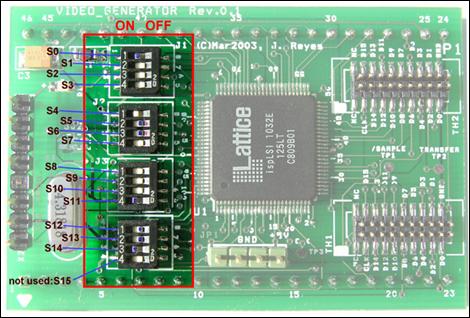
Figure 1: Configuration switches.
If [D15:D0]
represents the bits of the generated 16-bit pixels, the switches are mainly
used to configure [D15:D0] in the following way:
- The 4 most significant bits of the
pixel, [D15:D12], can be configured to have a fixed digital value ranging
from [0000] to [1111]. This 4-bit field is meant to play the role of a
pixel offset. As we have 4 bits to set the pixel offset, a maximum of 16
distinguishable channels (4 video boards) can be programmed.
- Bits [D15:D0] can be programmed to
work as a 16-bit up- or down-counter.
- Bits [D2:D0] of the generated pixel
can be programmed to provide a pseudo-random noise.
- In addition, an arbitrary bit of the
set [D15:D0] can be forced to be 0 or 1. (Only one bit at the time can be
forced to be 0 or 1.) This feature is useful to track down stuck bits
along the digital chain.
A representation
of how a pixel can be composed with the switches is shown in Figure 2. In this figure the switches are represented by S0 to
S14.
Figure 2 shows how the structure of the pixel generator
consists essentially of a counter to which the following logic has been added
in consecutive stages:
·
A 3-bit noise generator has
been added to the 3 least significant bits of the counter.
·
Logic to set or reset a
particular bit. When the logic is enabled, the bit can be forced to be 0 or 1.
·
Logic in order to set the 4 most
significant bits of the output word [D15:D0].
Figure 2: Configuration
switches.
Pay special
attention to the precedence taken by the setting. For example, if we have
configured the pixel generator to be a binary counter and bits [D15:D12] to
have a fixed offset value, the bits of the offset take precedence over the bits
from the counter and the situation would be equivalent to having a 12-bit
counter [D11:D0] mounted on an fixed offset [D15:D12]. Or for example, if the least
significant bits of the pixel, [D2:D0], are configured to simulate random noise
and in addition, we force bit D2 to be always 1, the forced bit takes
precedence over the bit D2 of the noise generator and we would be actually generating pixels with
only the 2 least significant bits simulating the noise.
- Use switch S5 to enable the counter
on and off.
- Use switch S10 to count up (S10=off)
or down (S10=on).
- Use switch S7 to activate the self
reset of the counter. (See Section 6 below for more details.) If S7 is enabled, the
counter can reset itself depending on the position of switch S8:
- Set S8 to off to have the self
reset after 2 seconds from the last generated pixel.
- Set S8 to on to have the self
reset after 4 seconds from the last generated pixel.
3
Setting
up the noise generation
- Use switch S6 to enable the noise
generation.
Remember that
the noise generation takes precedence over the counter.
- Set S9 to on to force a particular
bit to be 0 or to 1. If S9 is enabled, S10 will work as follow:
- Set S10 to off to force the
particular bit to 0.
- Set S10 to on to force the
particular bit to 1.
- Set switches [S14:S11] to the
position of the bit to be forced according to the following table:
|
S14
|
S13
|
S12
|
S11
|
Position of bit forced
|
|
0
|
0
|
0
|
0
|
Bit 0
|
|
0
|
0
|
0
|
1
|
Bit 1
|
|
0
|
0
|
1
|
0
|
Bit 2
|
|
0
|
0
|
1
|
1
|
Bit 3
|
|
0
|
1
|
0
|
0
|
Bit 4
|
|
0
|
1
|
0
|
1
|
Bit 5
|
|
0
|
1
|
1
|
0
|
Bit 6
|
|
0
|
1
|
1
|
1
|
Bit 7
|
|
1
|
0
|
0
|
0
|
Bit 8
|
|
1
|
0
|
0
|
1
|
Bit 9
|
|
1
|
0
|
1
|
0
|
Bit 10
|
|
1
|
0
|
1
|
1
|
Bit 11
|
|
1
|
1
|
0
|
0
|
Bit 12
|
|
1
|
1
|
0
|
1
|
Bit 13
|
|
1
|
1
|
1
|
0
|
Bit 14
|
|
1
|
1
|
1
|
1
|
Bit 15
|
5
Setting
the offset of the frame
- Move switch S0 to ON to generate
pixels with a 4-bit offset.
- Use switches [S4:S1] to set the
desirable offset. Switches [S4:S1]
map directly to [D15:D12].
The clock of the
counter is connected to the /sample signal of the ADC so
that the pixel generator, when configured as a counter, counts up or down from
pixel to pixel. The count value wraps around when it reaches the count 0xFFFF
(when counting up) or 0x0000 (when counting down). The counter will therefore generate
the following sequence:
|
|
Counter
counting up
|
Counter
counting down
|
|
Pixel n
|
0xFFFD
|
0x0001
|
|
Pixel n+1
|
0xFFFE
|
0x0000
|
|
Pixel n+2
|
0xFFFF
|
0xFFFF
|
|
Pixel n+3
|
0x0000
|
0xFFFE
|
|
Pixel n+4
|
0x0001
|
0xFFFD
|
However, the
counter does not know anything about the beginning of a frame and therefore, in
most of the cases the first pixel of a frame will be neither zero nor always
the same value. See Figure
3. This feature is useful if we want the value of the
first pixel of frame N+1 to be one more (when counting up) than that of the
last pixel of frame N.
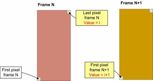
Figure 3: Frame-to-Frame
pixel value when counter is not reset.
Nonetheless, in
some other situations it is useful to configure the pixel generator as a
counter starting always from zero at the beginning of a frame. In order to do
this, the counter on the pixel generator must be configured with the switches
to reset itself after 2 or 4 seconds (switch on S7 to enable this feature and
set S8 on or off to reset after 2 or 4 seconds respectively) starting from the
generation of the last pixel from the previous frame. Figure 4 depicts the reset of the counter between consecutives
frames.
It means that we
need a pause of at least 2 or 4 seconds between consecutive frames to allow the
counter to reset itself and have frames with the first pixel starting from
zero. (The reason why the counter cannot be reset at will is that the pixel
generator is plugged on the socket of the ADC and on the video board there is
no additional control signal available to do a reset of the module in a
controlled way.)
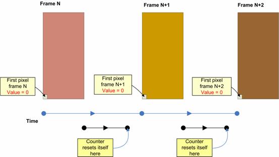
Figure 4: Counter self reset after 2
or 4 seconds.
In summary, the
self reset of the counter is configured as follows:
- S5=on, S7=on, S8=off à Counter resets after 2 seconds from the last pixel of a frame.
- S5=on, S7=on, S8=on à Counter
resets after 4 seconds from the last pixel of a frame.
7
Note
on the functionality of switch S10
As can be seen
in Section 2 and Section 4, switch S10 has a double functionality.
- When switch S9 is off (no bit is
forced), S10 is used to set the counter to count up or down. That is to
say:
- S5=on, S9=off, S10=off à Counter counting up.
- S5=on, S9=off, S10=on à Counter counting down.
- When switch S9 is on (output bit is
forced), S10 is used to force the bit to 0 (S10=off) or to 1 (S10=on).
8
Some
examples
- Example 1: Simulate a
flat field frame consisting in an offset of 0xA000 and random noise
on the 3 least significant bits. The switches setting should be as follow:
·
S0=on (offset on)
·
[S4:S1]=[1010] (4 most significant bits = 0xA)
·
S5=off (counter disabled)
·
S6=on (noise generation enabled)
·
S7=off (no active reset)
·
S9=off (no forced bit)
An example of the pixel sequence with this configuration is:
|
Pixel 0
|
0xA3E5
|
|
Pixel 1
|
0xA3E1
|
|
Pixel 2
|
0xA3E7
|
|
Pixel 3
|
0xA3E8
|
|
Pixel 4
|
0xA3EF
|
|
Pixel 5
|
0xA3E9
|
|
Pixel 6
|
0xA3E0
|
|
…
|
0xA3E0
|
Note how the most significant bits
are 0xA (as intended), the 3 least
significant bits are noise, but bits [D11:D3] are not zero necessarily as we
have not set S7 to on to reset the counter, therefore bits [D11:D3] contain
whatever un-initialized value.
- Example 2: Setting up a 16-bit
counter with self reset after 2 seconds between frames, no noise
generation, no forced bit and no offset:
·
S0=off (offset off)
·
[S4:S1]=[XXXX] (4 most significant bits = don’t
care)
·
S5=on (counter enabled)
·
S6=off (noise generation disabled)
·
S7=on (active reset enabled)
·
S8=off (self reset after 2 seconds)
·
S9=off (no forced bit)
·
S10=off (It does not matter)
An example of the pixel sequence with this configuration is:
|
Pixel 0
|
0x0000
|
|
Pixel 1
|
0x0001
|
|
Pixel 2
|
0x0002
|
|
Pixel 3
|
0x0003
|
|
Pixel 4
|
0x0004
|
|
Pixel 5
|
0x0005
|
|
Pixel 6
|
0x0006
|
|
…
|
…
|
- Example 3: Setting up a 16-bit
counter mounted on an offset of 0x3, no noise
generation, counter self reset every 4 seconds and forcing bit number #10
of the pixel to 1:
·
S0=on (offset on)
·
[S4:S1]=[0011] (4 most significant bits = 0x3)
·
S5=on (counter enabled)
·
S6=off (noise generation disabled)
·
S7=on (active reset of the counter on)
·
S8=on (self reset after 4 seconds)
·
S9=on (force bit activated)
·
S10=on (force bit to 1)
·
[S14:S11]=[1010] (force bit number #10 of [D15:D0])
·
S10=off (counter counting up)
An example of the pixel sequence with this configuration is:
|
Pixel 0
|
0x3400
|
|
Pixel 1
|
0x3401
|
|
Pixel 2
|
0x3403
|
|
Pixel 3
|
0x3404
|
|
Pixel 4
|
0x3405
|
|
Pixel 5
|
0x3406
|
|
Pixel 6
|
0x3407
|
|
…
|
…
|
|
…
|
…
|
|
Pixel n
|
0x37FD
|
|
Pixel n+1
|
0x37FE
|
|
Pixel n+2
|
0x37FF
|
|
Pixel n+3
|
0x3400
|
|
Pixel n+4
|
0x3401
|
|
…
|
…
|
|
…
|
…
|
Note how by forcing bit #10 to 1,
the sequence seems to jump back.
9
Some
notes
1
FIERA does not need to be put
offline or shutdown to change the switches of the pixel generator. They can be
changed on-the-fly.
2
The LED on the pixel generator
is to indicate that the module is on.
3
Pay attention to the way the
module is plugged on the board. See Figure
5.
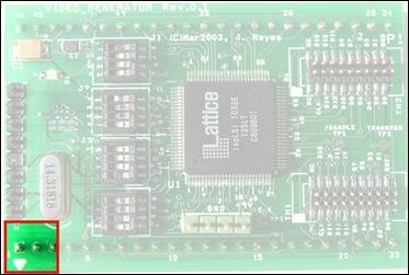
Figure 5: Position of the
pixel generator on the video board.
- Figure 6 shows some important tests points.
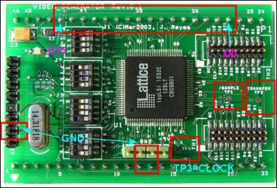
Figure 6: Oscilloscope ground
and test points.
10
Switch
configuration summary
|
Switch
|
Function
|
|
S0
|
Offset on/off
|
|
S4:S1
|
Offset value. [S4:S1] maps to [D15:D12]
|
|
S5
|
Counter on/off
|
|
S6
|
Noise generation on/off. Bits affected
[D2:D0]
|
|
S7
|
Active reset on/off
|
|
S8
|
Delay for the self-rest. On à reset after 2s. Off à reset after 4s
|
|
S9
|
Forced bit on/off
|
|
S10
|
Bit forced to 0 (S10=off), bit forced to
1 (S10=on)
|
|
[S14:S11]
|
Binary position of the bit to be forced
|
|
S10
|
If S9 not enabled: S10=off à counter up, S10=on à counter down.
|